The AANI-FB-0179-1 FPC antenna covers 5.15–5.925 GHz with ~3.7 dBi peak gain on a 50 Ω feed — a compact, flexible PCB antenna useful for Wi‑Fi 6E and CBRS client radios. Point: quick performance snapshot matters; Evidence: manufacturer datasheet lists the nominal band and peak gain; Explanation: these numbers drive link‑budget and placement choices for indoor APs and gateways.
Purpose: this note is a concise, engineer‑focused readout of the part’s datasheet, integration notes and procurement checklist. Point: readers will get key specs, integration guidance and a test checklist; Evidence: recommendations below are tied to documented datasheet parameters; Explanation: use this as a rapid evaluation sheet before prototype integration and procurement.
Quick overview & at-a-glance specs (background)
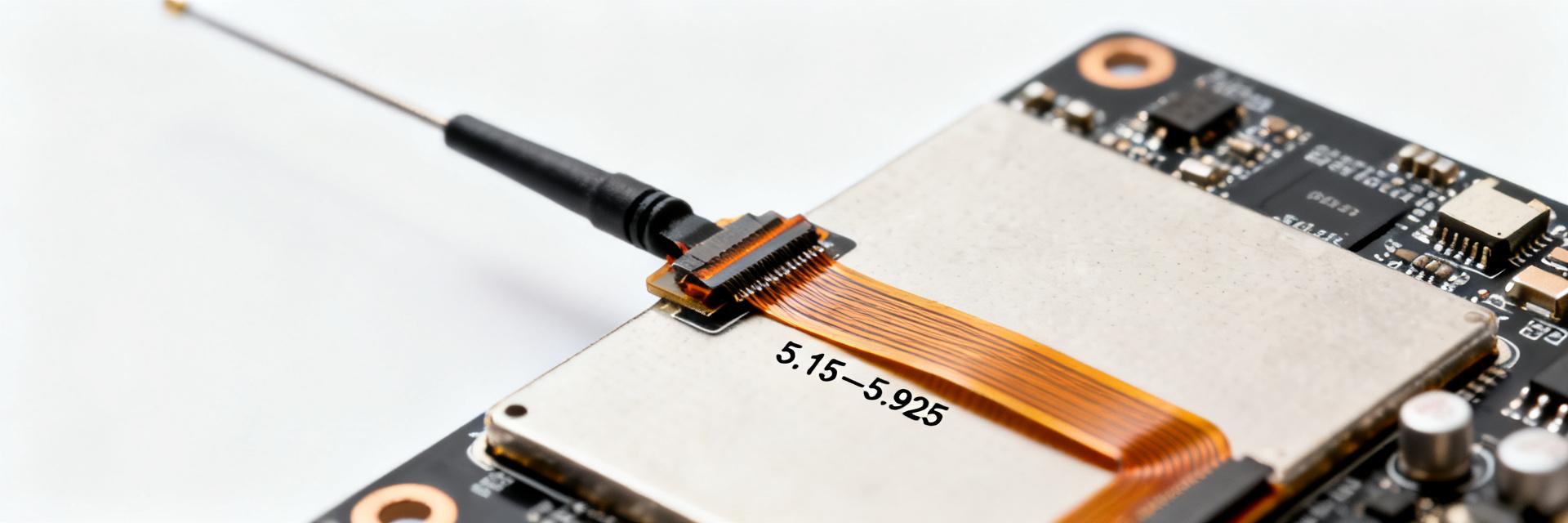
What the part is and target bands
Point: the component is a flexible PCB (FPC) antenna intended for sub‑6 GHz Wi‑Fi/5G/CBRS/GNSS combo use. Evidence: the nominal band is centered on 5.15–5.925 GHz as reported by the manufacturer. Explanation: the FPC antenna form factor favors internal mounting in client APs, indoor routers and compact gateway modules where low profile and light weight are priorities.
At-a-glance spec summary
Point: provide a compact spec list for quick verification; Evidence: typical datasheet fields include frequency span, gain, VSWR and mechanical data; Explanation: verify numeric values against the manufacturer datasheet before purchase.
| Spec | Typical value (verify in datasheet) |
|---|---|
| Frequency range | 5.15 GHz – 5.925 GHz |
| Peak gain | ~3.7 dBi (anechoic peak) |
| Typical VSWR / Return loss | ≤ 2.0 (S11 ≤ -6 dB typical) |
| Impedance | 50 Ω |
| Input power | ~1 W (confirm in datasheet) |
| Polarization | Linear |
| Dimensions | typical FPC strip format — verify L × W × thickness |
| Feed | Direct FPC tail / solder or IPEX mate (check part variant) |
| Operating temp | industrial range (verify) |
| Compliance | RoHS flag often listed — verify |
RF performance deep-dive (data analysis)
Frequency response, VSWR and bandwidth
Point: assess S11/return‑loss across the 5.15–5.925 GHz band to confirm usable bandwidth; Evidence: datasheet S11 plots show resonances and the usable VSWR window; Explanation: aim for VSWR < 2 across the required sub‑band, annotate resonant dips, and flag any band edges where S11 degrades for system‑level decisions.
Gain, efficiency and radiation pattern specifics
Point: peak gain and efficiency determine link budget; Evidence: the manufacturer reports ~3.7 dBi peak — usually measured in anechoic conditions with recommended mounting; Explanation: convert antenna gain plus TX power to estimated range (example: 20 dBm TX + 3.7 dBi antenna ≈ EIRP baseline; account for cable/feed loss and receiver sensitivity when sizing links).
Electrical, mechanical & environmental limits (data analysis)
Electrical and connector details
Point: confirm impedance, power rating and any DC/ESD constraints before assembly; Evidence: typical FPC antennas are 50 Ω and low power‑rated—check manufacturer notes for ESD protection and recommended matching; Explanation: add series matching or ESD paths on the PCB if the datasheet suggests matching components or if on‑board tuning is expected.
Mechanical dimensions and reliability ratings
Point: mechanical fit and bend limits govern assembly; Evidence: datasheet diagrams specify L × W × thickness, minimum bend radius and mounting method (adhesive or bracket); Explanation: follow the recommended bend radius, use the specified adhesive, and include a dimension diagram in BOM documentation for assembly teams.
Integration & PCB layout best practices (method guide)
Placement, ground plane & clearance rules
Point: placement relative to ground plane and metal is decisive for performance; Evidence: OEM integration notes in the datasheet typically list minimum clearances and ground plane extents; Explanation: leave a keepout region around the antenna (example: several mm clearance), reserve a predictable ground plane area, and avoid metal directly above the FPC antenna to prevent detuning.
Feed, matching, routing and EMI mitigation
Point: preserve a 50 Ω feed and limit common‑mode currents; Evidence: datasheet recommends feed routing and shows where matching components belong; Explanation: route the feed as controlled microstrip or short coax, place matching/test pads near the feed, and use ferrite beads or common‑mode chokes to mitigate conducted noise from nearby digital traces.
Validation, testing & troubleshooting checklist (method guide)
Recommended lab tests and acceptance criteria
Point: define measurable pass/fail criteria before production; Evidence: common thresholds include VSWR < 2.5 or S11 < -6 dB across required band portions, plus OTA pattern validation; Explanation: run S11 on assembled boards, anechoic chamber patterns at center and edges, OTA throughput tests, and record fixture IDs for repeatability.
Common failure modes and mitigation steps
Point: anticipate detuning and mechanical issues; Evidence: typical failures are detuning from nearby metal, adhesive failure, and feed mismatches noted in field troubleshooting; Explanation: remediate by checking feed continuity, swapping a reference antenna, confirming adhesive bond, and re‑running S11 with incremental ground plane changes.
Application scenarios & procurement checklist (case study + action)
Typical application scenarios (short case examples)
Point: match bandwidth and form factor to use case; Evidence: the antenna’s wide 5.15–5.925 GHz span and modest gain favor indoor APs and compact gateways; Explanation: ideal for Wi‑Fi 6E client APs and CBRS indoor gateways; avoid for exposed outdoor masts or high‑vibration external installs where rugged radomes and cable‑mounted antennas are preferred.
Datasheet-to-purchase checklist (actionable procurement items)
Point: verify critical procurement items before ordering; Evidence: checklist items should be cross‑checked with the manufacturer datasheet; Explanation: confirm exact frequency coverage, connector/feed type, dimensional fit, environmental ratings, sample availability, recommended adhesive, and any suggested tuning procedures with sourcing.
Summary
Point: the AANI-FB-0179-1 delivers a compact FPC antenna solution for 5.15–5.925 GHz client and gateway use; Evidence: manufacturer datasheet lists the band, ~3.7 dBi peak gain and 50 Ω feed; Explanation: use the datasheet values for initial budget estimates, then validate on the assembled PCB with S11 and OTA tests before qualification.
- Confirm frequency coverage and peak gain from the datasheet against your system band plan; include margin for feed/cable loss.
- Follow placement and ground‑plane keepout rules to avoid detuning; plan test fixtures that replicate final enclosure.
- Run S11 on assembled boards and anechoic patterns at center and edges; log fixture ID, date, S11 and pass/fail thresholds for traceability.
Next step: run an S11 measurement on the assembled board with the minimal ground plane, then validate OTA throughput in an anechoic test to finalize integration choices.
FAQ
What are the critical mounting constraints for AANI-FB-0179-1?
Mounting constraints include adhering to the minimum bend radius, using the specified adhesive method, and maintaining the recommended keepout from metal and large ground pours. Verify the exact L×W×thickness and minimum bend radius in the manufacturer datasheet before final bracket and enclosure design.
How should I verify RF performance for AANI-FB-0179-1 on my PCB?
Perform S11/return‑loss on the assembled board (test pad at feed), then run anechoic chamber radiation patterns at center and band edges and OTA throughput tests to correlate lab metrics with system performance. Record fixture IDs and environmental conditions for each run.
What matching circuit and detuning mitigation steps should be planned?
To mitigate detuning, reserve a Pi-matching network layout directly at the feed trace. Route the trace as a 50-ohm coplanar waveguide or microstrip, keep a clear keepout zone around the antenna, and isolate high-speed digital lines with shielding or common-mode filters.
What procurement checks should be done for AANI-FB-0179-1 before ordering?
Confirm exact frequency coverage, feed/connector variant, dimensional fit, operating temperature range, RoHS/compliance flags, lead time and sample availability. Ask sourcing for recommended adhesive, mating connector type if applicable, and any known tuning guidance from the manufacturer.


