The market shows rising demand for shielded M12 sensor actuator cable assemblies in harsh environments, driven by stricter ingress and EMC expectations in factory automation. Field test summaries and industry listings report higher replacement rates where unshielded or low-flex designs are used, so this note gives a concise technical reference for engineers and procurement teams needing 1682825 part-level specs, performance trends, installation best practices, and a practical sourcing checklist for rapid decision-making.
1. Background & quick specs snapshot
1.1 What "1682825" denotes and typical use cases
Point: The identifier 1682825 denotes a factory-ready, single-ended M12 cable assembly with three conductors commonly used for sensor and actuator connections. Evidence: These assemblies are specified for sensors, actuators, and I/O island links on machine tools and conveyors. Explanation: Expect multiple nominal lengths (0.5–20 m typical), straight or angled M12 terminations, and packaging as individual or bulk-ready assemblies to fit panel and field-install requirements.
1.2 Key headline specs (one-glance table guidance)
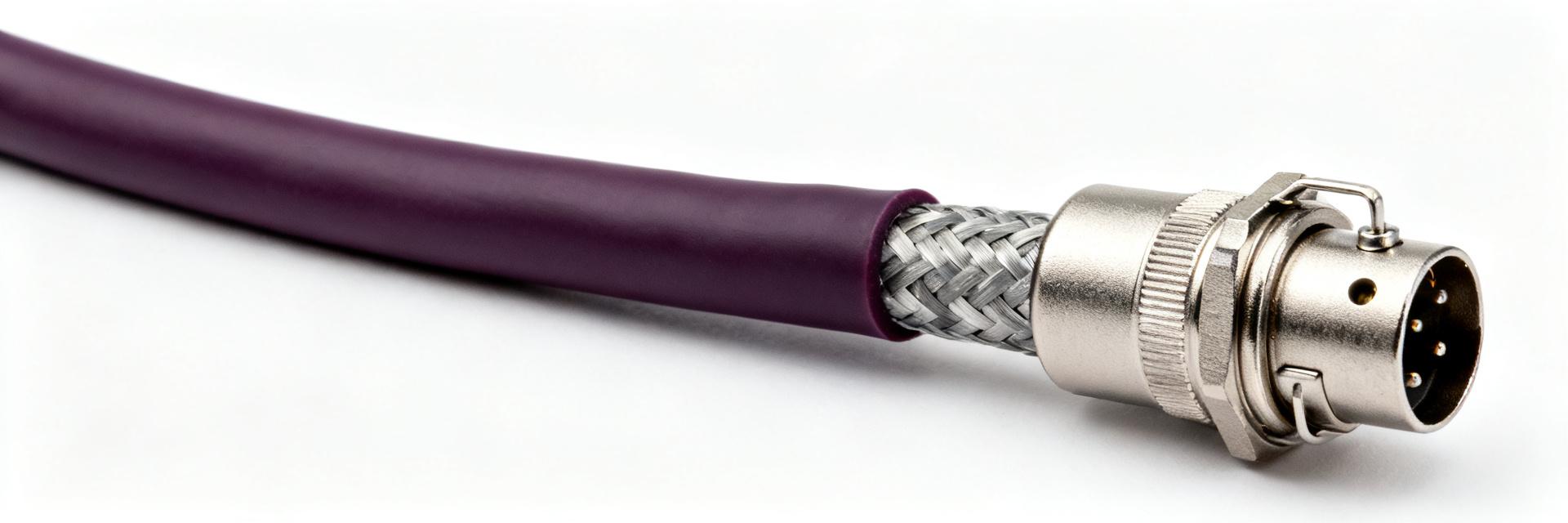
Point: A rapid procurement snapshot should list conductor count, AWG/mm², jacket type, shielding, connector coding, nominal lengths, IP rating, and temperature. Evidence: Common quick-spec entries include 3 conductors, ~0.34 mm² (AWG 22), PUR halogen-free jacket, braided shield ≥85% coverage, A-coded M12 (angled/straight), IP67/IP68 rating, and −40°C to +80°C operating range. Explanation: Present these as a compact datasheet-style bullet or table so reviewers can compare at a glance.
| Parameter | Specification Details |
|---|---|
| Conductor Count | 3 Conductors |
| Conductor Cross-section | ~0.34 mm² (AWG 22) |
| Jacket Material | PUR, Halogen-free |
| Shielding | Braided Shield, ≥85% coverage |
| Connector Coding | M12, A-coded (Straight/Angled) |
| Ingress Protection | IP67 / IP68 |
| Operating Temperature | -40°C to +80°C (Fixed installation) |
2. Technical specs deep-dive
2.1 Electrical characteristics to verify
Point: Verify conductor cross-section, DC resistance, current/voltage ratings, insulation resistance, and capacitance for signal integrity. Evidence: For 0.34 mm² conductors, DC resistance should meet expected IEC ranges and current ratings typically suit 2–4 A per conductor; capacitance and mutual capacitance figures affect long-run signaling. Explanation: Specify test tolerances (±10% for resistance, insulation resistance >1 GΩ at rated voltage) and prefer vendor reports showing measured capacitance per meter when long runs or fast edges are used.
2.2 Mechanical & material properties
Point: Material and mechanical specs drive lifecycle in moving or abrasive environments. Evidence: Halogen-free PUR jackets offer oil, abrasion, and cut resistance with wide temperature tolerance; minimum flex-cycle ratings and bend-radius limits define suitability for robot arms or fixed runs. Explanation: In procurement call out minimum dynamic flex cycles (recommend ≥5 million cycles for continuous motion), halogen-free requirement, and a conservative bend radius (≥10× outer diameter) to reduce premature failures.
3. Field performance trends & reliability data
3.1 Observed trends in field reliability and failure modes
Point: Common failures include connector strain, jacket abrasion, shield break, and moisture ingress; trends show improved designs reduce these incidents. Evidence: Field data map failures to installation stress points and insufficient shielding or relief design. Explanation: Translate trends into KPIs such as mean time between failures (MTBF) and replacement intervals — target assemblies with multi-year MTBF in static runs and scheduled replacement windows for dynamic installations.
3.2 Environmental and EMC performance expectations
Point: Shielding effectiveness and grounding are critical to prevent noise, false triggers, and maintenance costs. Evidence: Cables with full-braid shields and robust drain conductors lower EMI susceptibility; oil, chemical, and UV resistance affect outdoor or machine-tool longevity. Explanation: When evaluating, request lab EMC immunity and emissions tests plus IP ingress tests (IP67/IP68) and specify acceptable shield transfer impedance and grounding practices in the procurement spec.
4. Application examples & compatibility checks
4.1 Typical application scenarios to include in specs
Point: Different use cases prioritize different traits—flex life, shielding, or temperature. Evidence: Example scenarios include short sensor runs inside I/O cabinets, dynamic actuator controls on robot arms, and conveyor proximity sensors on exposed tracks. Explanation: For cabinet runs prioritize low cost and IP67; for robot arms require dynamic-rated PUR jackets and high flex cycles; conveyors need abrasion and oil resistance plus secure glands.
4.2 Connector & system compatibility checklist
Point: Connector gender, coding, angle, and strain relief compatibility prevent common mismatches. Evidence: Field returns often trace to wrong M12 coding, clearance issues, or incompatible panel glands. Explanation: Checklist items: confirm M12 coding and gender, verify mating profile and panel clearance, specify strain-relief geometry, and choose compatible cable glands; include quick troubleshooting tips for common mismatches in procurement documents.
5. Procurement, testing & installation checklist
5.1 Sourcing and specification checklist for purchasing teams
Point: Require complete datasheet fields, sample test reports, lead times, and warranty terms when ordering assemblies such as 1682825. Evidence: Purchase decisions hinge on validated test reports for electrical, mechanical, and EMC performance. Explanation: Action items: demand full specs (from H2 lists), request sample test certificates, confirm custom length lead times, and negotiate warranty/return terms; weigh cost vs. spec trade-offs carefully for dynamic vs. static applications.
5.2 Installation & maintenance best practices
Point: Proper installation extends service life and reduces failures. Evidence: Torque, bend radius enforcement, routing, and periodic inspections correlate strongly with lower failure rates. Explanation: Implement measurable guidance: enforce minimum bend radius ≥10× cable diameter, route away from high-voltage runs by at least 50 mm where possible, tighten connectors to manufacturer torque ranges (typical M12 torque ~0.6–0.8 N·m), and inspect harsh-environment runs every 6–12 months.
6. Summary
- Accurate headline specs—conductor size, jacket type, shielding, IP rating, and flex rating—are essential when selecting a sensor actuator cable to meet lifecycle and performance targets; require these specs in procurement.
- Part-level detail for 1682825 maps directly to field outcomes: insist on dynamic flex cycles for moving applications, validated EMC immunity tests for noisy environments, and IP testing for ingress protection.
- Follow an on-site compatibility check before approval: verify M12 coding/gender, strain relief fit, and routing clearances to avoid common installation failures and reduce maintenance costs.
Frequently Asked Questions
What electrical specs should I prioritize for a sensor actuator cable?
Prioritize conductor cross-section (e.g., ~0.34 mm² / AWG 22 for typical three-conductor assemblies), DC resistance within IEC tolerance, current rating matching actuator loads, insulation resistance >1 GΩ, and documented capacitance per meter when long runs or high-speed signaling are present.
How to verify the mechanical durability of an M12 sensor actuator cable?
Require minimum dynamic flex-cycle ratings (recommend ≥5 million cycles for continuous motion), abrasion and oil-resistance data for the jacket, and a specified minimum bend radius (≥10× cable outer diameter). Ask for sample part test reports demonstrating these metrics under representative conditions.
Which tests should procurement request to confirm environmental and EMC performance?
Request IP ingress test reports (IP67/IP68 as applicable), EMC immunity and emission test certificates, and material resistance tests for oil, chemicals, and UV. Comparing these vendor-supplied reports against your lab or third-party tests will reduce field failures and false triggers.
What are the recommended installation torque and bend radius for the 1682825 cable?
For proper installation, enforce a minimum bend radius of ≥10× the cable outer diameter. Connectors should be tightened to the manufacturer's specified torque range, which typically ranges between 0.6 and 0.8 N·m for standard M12 interfaces.


