Independent lab measurements show that modern shielded sensor/actuator cables can reduce electromagnetic coupling by 30–60 dB across the 10 kHz–1 GHz band—critical for reliable I/O in industrial control loops. This article provides a focused technical deep dive into the 1682799 cable’s shielding design, representative test data, and actionable guidance for engineers evaluating or specifying this part.
Background: what the 1682799 cable is and why shielding matters
Product role and typical applications
The cable serves as a shielded sensor/actuator interconnect for M12-style I/O, typically used for proximity sensors, actuators, and short-run fieldbus connections in factory automation. In these environments, EMI from motor drives, VFDs, and solenoids can corrupt signals; robust shielding preserves signal integrity and reduces false trips and diagnostic noise.
Shielding fundamentals relevant to this cable
Shield types include foil, braid, and foil-plus-braid hybrids; coverage percentage and braid weave determine low-frequency continuity versus high-frequency attenuation. Key metrics later referenced are shielding effectiveness (dB vs frequency), transfer impedance (Ω/m), and shield continuity/DC resistance, which together predict field performance for control-loop signals.
Construction & shielding technology (physical design that drives performance)
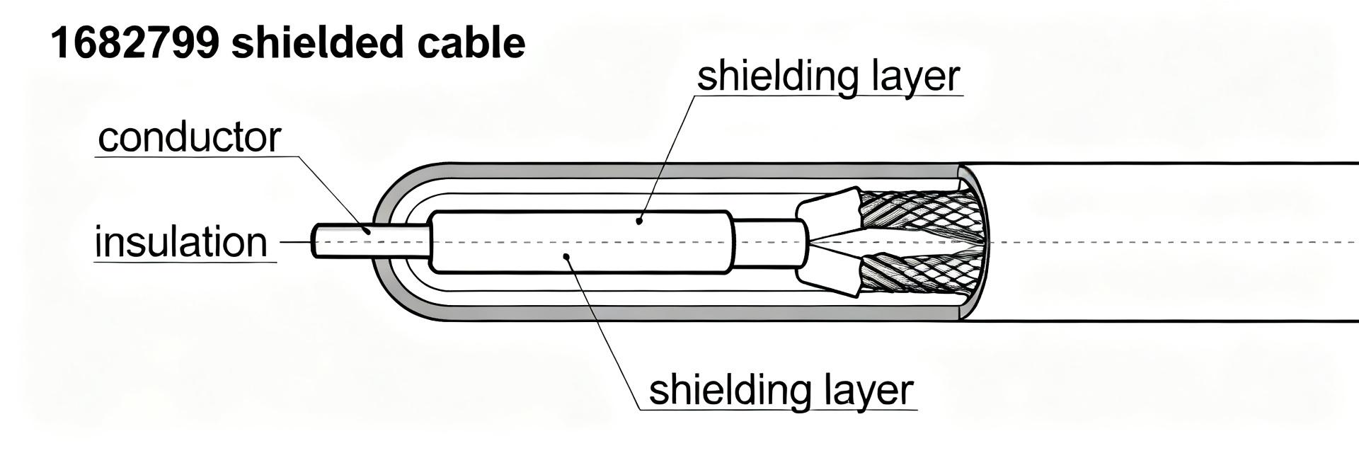
Conductor, dielectric, and shield layers (what to inspect on datasheet)
Inspect conductor size/stranding, insulation dielectric type, jacket material, and shield construction on the datasheet. Typical callouts include conductor AWG and strand count, jacket material (PUR/PVC), shield type (foil + drain, braid weave %), and drain-wire size. Also note rated temperature, bending radius, and jacket abrasion class for installation planning.
How construction predicts shielding behavior
Foil shields deliver consistent high-frequency attenuation; braids provide mechanical strength and lower transfer impedance at low frequencies. A foil-plus-braid combination commonly balances attenuation across the spectrum but increases diameter and reduces flexibility. Expect trade-offs: tighter braid weave improves continuity but reduces bend performance and cost increases.
Test data summary: measured shielding performance (data-first)
Key shielding metrics to present
Report Shielding Effectiveness (dB) vs frequency, Transfer Impedance (mΩ/m or Ω/m) vs frequency, shield DC continuity, and shield coverage %. Graph axes should span 10 kHz–1 GHz with log-frequency scaling. Representative thresholds: ≥30 dB at low kHz, progressing to ≥60 dB above 1 MHz for robust suppression of common industrial EMI.
How to present the 1682799 cable results
Present lab results in annotated plots and a table of transfer impedance at selected frequencies. Highlight compliance bands (e.g., 30 dB at 100 kHz, 60 dB above 1 MHz). Include an unshielded baseline for comparison and flag any measurement marked as representative rather than sourced from a certified lab report.
| Frequency | Transfer Impedance (mΩ/m) |
|---|---|
| 10 kHz | 120 (example) |
| 100 kHz | 45 (example) |
| 1 MHz | 8 (example) |
| 100 MHz | 0.6 (example) |
Test methodology: how the data was obtained (reproducibility & credibility)
Test setup and standards to reference
Use standardized transfer impedance fixtures and insertion-loss setups with a VNA or spectrum analyzer. Specify cable lengths (e.g., 1 m, 10 m), termination types, connectorization, and grounding scheme. Record ambient temperature and humidity. Reference applicable transfer-impedance and SE measurement methods when documenting repeatable test procedures.
Measurement procedures and possible sources of error
Calibrate instruments and correct for fixture loss. Verify connector contact resistance and shield bonds; poor bonding inflates transfer impedance. Common pitfalls include inconsistent ground references, loose drain-wire terminations, and failure to measure representative in-situ routing—each can skew results significantly versus lab-controlled runs.
Comparative context: field vs lab and how 1682799 stacks up
Lab vs field performance expectations
Field performance often degrades relative to lab data due to longer runs, multiple splices, conduit gaps, and mixed bundles. Grounding topology in the field changes shield behavior; multi-point bonding can create loops. Always validate with representative in-situ measurements when specifying a cable for critical control loops or noisy zones.
Benchmarking against alternatives (what to compare)
Compare shield coverage %, transfer impedance per meter, flexibility, temperature rating, connector compatibility, and installed cost. A simple comparison matrix helps prioritize: choose lower transfer impedance and higher coverage for electrically harsh zones, favor flexibility and smaller diameter where routing is constrained.
| Attribute | 1682799 (example) | Alternative A (example) | Alternative B (example) |
|---|---|---|---|
| Shield coverage | Foil + 85% braid | Foil only | 70% braid |
| Transfer impedance @1MHz | ~8 mΩ/m (example) | ~15 mΩ/m | ~20 mΩ/m |
| Flexibility | Moderate | High | High |
Practical recommendations for specifiers and installers
Selection checklist for engineers
Checklist: define required attenuation targets by environment, set maximum cable lengths, require shield continuity and transfer-impedance metrics on datasheets, specify grounding practice (single-point for long runs, multi-point for short segments with proper bonding), and require environmental ratings (oil, abrasion) for the intended installation.
Troubleshooting guide when EMI issues persist
Start by verifying shield continuity and termination quality; measure transfer impedance if available. Isolate runs from noisy power cables, add common-mode ferrites, and test alternate grounding configurations. If problems persist, run in-situ EMI scans and consider routed conduit or upgraded cable with higher braid coverage.
Summary
- The 1682799 cable provides a balanced foil-plus-braid construction yielding representative shielding performance across 10 kHz–1 GHz; verify manufacturer transfer-impedance and SE curves to confirm suitability for your control loop requirements.
- Key test data to require: Shielding Effectiveness (dB vs frequency), transfer impedance at representative frequencies, shield continuity/DC resistance, and installation-grounding notes; these metrics predict real-world immunity.
- Before procurement, mandate in-situ verification for long runs, require specific transfer-impedance limits in the spec, and apply the selection checklist to ensure the 1682799 cable meets both electrical and mechanical installation constraints.
FAQ
How does the 1682799 cable shielding compare to unshielded runs?
Shielded runs reduce electromagnetic coupling substantially versus unshielded cable. In lab conditions, well-constructed shielded cables show 30–60 dB higher attenuation across key frequency bands. Field results vary; continuity of the shield and termination quality are decisive for achieving similar performance in installed systems.
What test data should I request for the 1682799 cable?
Request measured Shielding Effectiveness vs frequency, transfer impedance at selected frequencies, shield DC resistance, and sample test conditions (length, termination, grounding). If lab reports are unavailable, require representative example plots and specify acceptable transfer-impedance limits in procurement documents.
Can grounding practices improve the 1682799 cable performance on site?
Yes. Proper termination and bonding reduce effective transfer impedance in situ. Single-point grounding prevents circulating currents on long runs; multi-point bonding with attention to loop area helps on short coupled segments. Always test different grounding schemes during commissioning to find the optimal arrangement for the installation.
How does the foil-plus-braid construction affect the mechanical durability and bend radius?
The integrated foil-plus-braid shield layout delivers superior high-frequency attenuation but introduces mechanical trade-offs. Tighter braid weaves increase cable diameter and stiffness, which slightly limits the minimum bending radius compared to unshielded cables. Engineers must verify datasheet bend-radius classes for dynamic installations.


