Based on a cross-sheet comparison of common M12 sensor cable datasheets and typical spec ranges, this roundup extracts the measurable metrics engineers rely on when specifying 1682809 variants. Readers get clear numeric ranges, test thresholds, and decision rules to speed selection and avoid mismatches. The focus is practical: what to check on a spec sheet and which thresholds trigger system revalidation for an M12 sensor cable.
1 — Why 1682809 M12 Sensor Cable Specs Matter (Background)
1.1 — Use cases and system impact
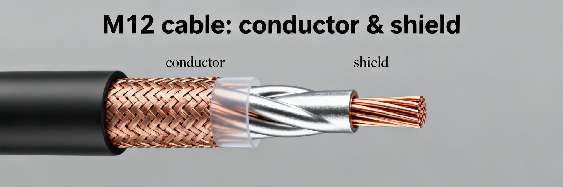
Point: Three‑wire M12 assemblies appear in sensors, actuators, and factory I/O where power, signal and ground share a round cable. Evidence: small conductor sizes and limited shielding increase voltage drop and EMI risk. Explanation: For I/O racks and distributed sensors, cable choice affects signal integrity, uptime, and installation cost through rework. When specs change beyond listed thresholds, plan system‑level revalidation.
1.2 — How to read an M12 cable spec sheet
Point: Key spec sections are conductor, insulation, shielding, connector pinout, and mechanical ratings. Evidence: fast checklist items—conductor mm²/AWG, DC resistance @20°C, capacitance pF/m, shield type/coverage, connector coding, IP rating, temperature and bend radius. Explanation: If voltage, temperature, or impedance on the sheet fall outside your application window, flag for engineering review before ordering.
2 — Electrical Metrics: Conductor, Resistance, Capacitance, and Impedance (Data analysis)
2.1 — Conductor size, DC resistance, and current capacity
Point: Typical 3‑core M12 sensor cables use conductors in the 26–22 AWG range (≈0.14–0.34 mm²). Evidence: DC resistance at 20°C therefore ranges roughly 0.12–0.05 Ω/m (ρCu≈0.0172 Ω·mm²/m). Explanation: Use Vdrop ≈ I × R to estimate drop; for a 1 A sensor over 10 m with 0.12 Ω/m, Vdrop ≈1.2 V, which can exceed sensor tolerance. Specify conductor ≥0.25 mm² for longer runs or >1 A currents.
| Conductor Size | Typical AWG Equivalent | Max DC Resistance (@20°C) | Recommended Max Run Length |
|---|---|---|---|
| 0.14 mm² | 26 AWG | ~0.12 Ω/m | < 5 meters |
| 0.25 mm² | 24 AWG | ~0.08 Ω/m | 5 to 10 meters |
| 0.34 mm² | 22 AWG | ~0.05 Ω/m | 10 to 20 meters |
2.2 — Capacitance, impedance, and signal integrity for sensor lines
Point: Capacitance typically falls in the 50–120 pF/m range for small multi‑core M12 cables; characteristic impedance often unspecified unless designed for fieldbus. Evidence: higher capacitance loads slow analog edges and attenuate high frequencies. Explanation: For analog sensors and fieldbus (CAN/RS‑485), prefer cables with documented low capacitance or controlled-impedance pairs; test with an LCR meter at recommended frequencies (1 kHz–1 MHz) to validate.
3 — Shielding, Grounding, and EMC Performance (Data analysis)
3.1 — Shield type and coverage: braid vs. foil vs. combined
Point: Shield categories include foil (~100% theoretical coverage), braid (≈70–95% coverage), and combined foil+braid (≈90–98% practical). Evidence: braid yields superior mechanical robustness; foil gives better high‑frequency screening. Explanation: For noisy motor/drive environments choose a shielded sensor cable with combined layers; braid improves termination reliability while foil helps at RF frequencies.
3.2 — Grounding/termination best practices and common failure modes
Point: Shield termination choices (single‑end, both‑ends, drain wire) affect EMC. Evidence: single‑end termination is common to avoid ground loops; both‑ends can be used where low impedance is needed and grounding is consistent. Explanation: Poor terminations cause intermittent noise—inspect for incomplete braid clamping, missing drain conductor, or loose connector seals during field diagnosis.
4 — Mechanical & Environmental Specs: Jacket, Temperature, Bending, and IP Ratings (Method/guide)
4.1 — Jacket material, abrasion, and chemical resistance
Point: Common jackets are PUR (high abrasion and oil resistance), PVC (cost effective), and halogen‑free variants for safety zones. Evidence: PUR typically outlasts PVC in flex and abrasion testing and resists oils and solvents better. Explanation: Select PUR for cable tracks and exposed routing; choose halogen‑free where fire safety regulations demand reduced smoke and toxic gas emissions.
4.2 — Temperature range, flex life, and minimum bend radius
Point: Typical operating ranges span −40°C to +80°C for general sensor cables; static variants may go higher. Evidence: continuous-flex products specify cycle life (10⁵–10⁶ cycles). Explanation: Use a bend‑radius rule of thumb: static ≥6× cable diameter, dynamic/flex ≥10×; exceed these minima during routing to avoid premature conductor or jacket fatigue.
5 — Connector, Pinout, and Mechanical Interface Details (Case/case-study style)
5.1 — M12 connector coding, pinout, and mating considerations
Point: M12 codings (A, B, etc.) distinguish signal families; 3‑pin sensor/actuator wiring commonly follows brown = +V, blue = 0 V, black = signal (verify device). Evidence: thread type and gasket compression determine IP rating; typical torque ranges for M12 threaded shells are about 0.5–1.0 N·m. Explanation: Follow torque and sealing guidance to maintain IP protection and avoid connector damage.
5.2 — Length options, prewired vs free cable end trade-offs
Point: Factory‑terminated assemblies provide traceability and consistent impedance; field‑terminate offers flexibility. Evidence: factory terminations reduce assembly error but raise lead time. Explanation: Choose prewired for critical runs and long lengths; if field termination is used, perform continuity, insulation resistance, and shield continuity tests post‑termination to validate integrity.
6 — Spec Checklist & Selection Workflow (Actionable guidance)
6.1 — Quick numeric checklist for specifying 1682809 M12 sensor cable
Point: Mandatory fields to confirm before ordering: conductor size (0.14–0.34 mm² / 26–22 AWG), shielding type (foil/braid/combined), jacket (PUR/PVC/halogen‑free), operating temp (−40°C to +80°C), IP (IP67/IP68), connector coding, length, and minimum bend radius. Evidence: use suggested numeric ranges and mark uncertain items for datasheet confirmation. Explanation: For many installations the right balance is a shielded, PUR‑jacketed assembly with ≥0.25 mm² conductors.
6.2 — Testing and verification steps before deployment
Point: Minimum test plan: continuity, insulation resistance, shield continuity, and a short functional run under load. Evidence: continuity catches opens; IR (megohm range) verifies insulation; shield continuity confirms termination. Explanation: In the field, if noise or intermittent faults appear, isolate by swapping to a known‑good cable and rechecking grounding, shield termination, and connector torque as first steps.
Summary
For 1682809 selections prioritize conductor size, shielding, and mechanical ratings: use conductors ≥0.25 mm² for longer/loaded runs, prefer combined braid+foil shielding for harsh EMC environments, and specify PUR jackets with bend radii ≥10× diameter for dynamic runs. A single‑line checklist: confirm conductor, shield type, jacket material, IP/temp ratings, connector coding, and minimum bend radius before ordering an M12 sensor cable.
Key Summary
Conductor Optimization
Choose 0.14–0.34 mm² (26–22 AWG). For lengths >10 m or loads >0.5–1 A, prioritize ≥0.25 mm² conductors to mitigate voltage drop using Vdrop ≈ I×R.
EMC Shielding
Select combined foil+braid shielding. This configurations delivers the optimal balance of dynamic flexibility and robust RF protection in electrical noise areas.
Mechanical & Jacket
Prefer PUR jackets over PVC for dynamic flex tracks. Maintain a standard operating limit of −40°C to +80°C and adhere strictly to standard bend radii configurations.
Frequently Asked Questions
What conductor size is used in 1682809 M12 sensor cable?
Most variants use 26–22 AWG (≈0.14–0.34 mm²). For short, low‑current sensors 0.14–0.25 mm² is common; for longer runs or currents approaching 1 A, specify 0.25–0.34 mm² to reduce DC resistance (≈0.12–0.05 Ω/m) and keep voltage drop within device tolerance.
How should the shield be terminated on an M12 sensor cable?
Best practice is a single‑end connection to chassis ground at the controller side to avoid ground loops, using a drain wire clamped under the connector’s shield termination band. For installations needing lower common‑mode impedance, bond both ends only when grounding is controlled and equipotential.
What temperature range can an M12 sensor cable tolerate?
General‑purpose M12 sensor cables commonly rate −40°C to +80°C. Static cables may be specified to higher maximums; continuous‑flex types provide documented cycle life at operating temperatures. Verify the cable’s datasheet for exact operating and storage temperature limits before deployment.
What is the recommended bend radius for dynamic M12 sensor cables?
For static/fixed installations, the minimum bend radius is typically ≥6× the outer cable diameter. For dynamic or continuous-flex applications (such as cable tracks), use a dynamic bend radius of ≥10× the outer diameter to prevent premature fatigue of internal conductors and shielding.


