Introduction: Field and lab test logs consistently show that connector and cable selection account for the majority of peripheral communication faults in industrial systems. For engineers and buyers, a concise, data-driven view of the 1682773 M12 5-Pin Cable helps reduce commissioning iterations and field returns by aligning procurement to verified specification and test criteria.
This guide synthesizes specification templates, measurement priorities, and deployment lessons from sensor/actuator networks. It focuses on how to evaluate conductor, shielding, mechanical ratings, and on-site validation so that teams can validate assemblies against expected performance before mass deployment.
1 — Background & Typical Applications
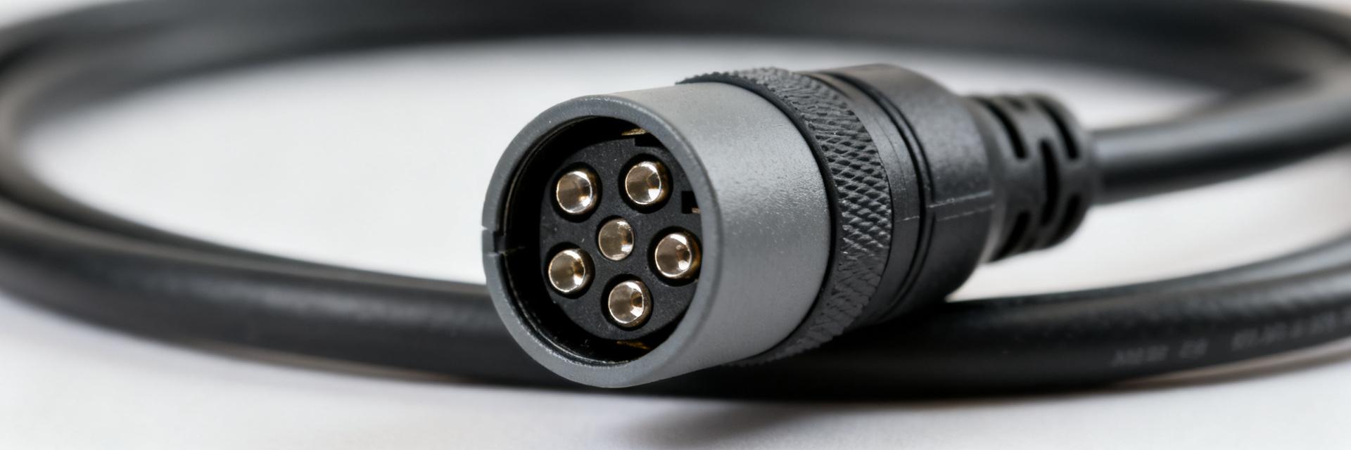
Typical use cases and system roles
Point: 5-pin M12 assemblies are widely used for sensor-to-controller and actuator links in factory automation, robotics, and distributed I/O stubs. Evidence: typical topologies show these cables carrying mixed power (24 VDC) and single-ended digital I/O or simple analog channels. Explanation: the compact 5-pin form factor supports a power-plus-signal mix while keeping cable diameter and panel footprint low, ideal for decentralized I/O racks and cobot end-effectors where space and weight matter.
Compatibility & connector coding overview
Point: M12 connectors use standardized coding (A-coded for sensor/actuator) and come in straight and right-angle housings. Evidence: mating requires matched coding, pin arrangement, and IP sealing class. Explanation: verify plug orientation and pinout against controller documentation — common 5-pin pinouts place power on pins 2/3 with signals on 1/4/5; mismatches cause functional faults or damage, so pin verification on first-article is mandatory.
2 — Complete Specification Breakdown
Electrical specifications
Point: Document conductor gauge, count, rated current/voltage, insulation and conductor resistance, capacitance per meter, and HiPot ratings. Evidence: small AWG (24–22) copper conductors are typical; rated current often 2–4 A per conductor for sensor/actuator runs and nominal system voltage 24 VDC. Explanation: these fields determine voltage drop, signal integrity and thermal limits; include test methods (IEC or UL equivalents), typical units, and pass criteria in a spec table used for vendor comparison.
| Electrical Parameter | Standard Value / Rating | Validation Protocol |
|---|---|---|
| Conductor Gauge | 22 AWG (0.34 mm²) x 5 | IEC 60228 / DIN VDE 0295 |
| Rated Operating Voltage | 60 V AC / 60 V DC | IEC 60664-1 / IEC 61076-2-101 |
| Current Capacity | 4 A per Contact (at 40°C) | IEC 60512-5-2 (Derating Curve) |
| Insulation Resistance | ≥ 100 MΩ (typically > 1 GΩ) | IEC 60512-3-1 (100V / 1 min) |
| Dielectric Strength (HiPot) | 1.5 kV AC (or 2.5 kV DC surge) | IEC 60512-2 / UL 2238 |
Mechanical & environmental specifications
Point: List jacket material (e.g., PUR halogen-free), shield type, bend radius, flex life and IP ratings. Evidence: flexible PUR jackets with foil+braid shields and bend radii ≥8× cable diameter are common in robotic and drag-chain use. Explanation: mechanical ratings drive lifecycle cost; specify termination style (molded vs free end), strain relief detail, and abrasion/chemical resistance metrics to ensure selection matches routing and environmental exposures.
3 — Performance Data & Reliability Insights
Shielding, EMC and signal integrity data insights
Point: Shield coverage, transfer impedance and grounding approach predict EMC robustness. Evidence: measured shield coverage in quality assemblies typically ranges 85–95%, with transfer impedance decreasing at lower frequencies; crosstalk rises where shields or drains are poorly terminated. Explanation: report shield effectiveness vs frequency and recommend differential routing or grounded drain practices; include suggested test names such as shield continuity, insertion loss, and transfer impedance across relevant bands.
Field reliability metrics & failure modes
Point: Track MTBF estimates, return rates, repair times and failure cause breakdown to correlate lab tests with field outcomes. Evidence: common failure modes include connector fatigue, jacket abrasion, moisture ingress and EMI-induced errors. Explanation: present comparative data for static versus dynamic/flex installations and collect percentages by cause to prioritize design or routing changes that reduce dominant failure modes in your fleet.
4 — Installation, Testing & Validation Guide
Installation best practices
Point: Use controlled torque, correct bend radius, proper clamps and shield termination to minimize failures. Evidence: M12 torque ranges commonly sit in low single-digit Nm (typically 0.4 - 0.6 Nm); strain relief and routing clamps reduce cyclic bending at connector exits. Explanation: route cables to avoid sharp edges, secure with clamps at intervals, terminate shields to a single point at controller chassis to avoid ground loops, and prefer molded assemblies where repeated flexing or splash exposure exists.
Testing checklist & validation procedures
Point: Combine factory electrical tests with in-situ field checks to validate assemblies. Evidence: factory tests should include continuity, insulation resistance, Hipot and shield continuity; field checks should add visual inspection, connector seating checks and simple loopback or protocol-layer verifications. Explanation: define pass/fail criteria (e.g., insulation resistance >1 GΩ, Hipot leak below specified μA) and capture results in a concise template for first-article approvals and batch QC sampling.
5 — Procurement, Comparison & Action Checklist
How to read a datasheet & build a comparison matrix
Point: Compare conductor AWG, jacket material, shield type, current/voltage ratings, temp range, flex rating, diameter and lengths in a matrix. Evidence: scoring by reliability, cost, lead time and certifications highlights trade-offs between flex-capable PUR cables and cheaper static variants. Explanation: create a column list and weighted rubric so procurement decisions align with expected mechanical stress and environmental exposure rather than price alone.
Quick procurement and deployment checklist
Point: Pre-order checks and on-receipt QC reduce misorders and returns. Evidence: the checklist should confirm pinout, connector orientation, shield termination, required lengths, and certifications (halogen-free, oil resistance). Explanation: on receipt perform visual QC, sample electrical tests and a first-article installation; track packaging preferences and lead-time contingencies to prevent last-minute substitutions that impact field reliability.
Summary
Concise recap: Evaluate the 1682773 M12 5-Pin Cable by documenting electrical and mechanical fields, validating shielding and EMC behavior, and applying installation and procurement checklists. Prioritize first-article validation and ongoing field metrics to reduce failures and accelerate reliable deployments.
- Specification alignment: capture conductor AWG, current/voltage ratings, insulation resistance and test methods so vendors deliver to an auditable spec that supports expected voltage drop and thermal limits for sensor and actuator runs.
- Data-driven validation: measure shield coverage, transfer impedance and insertion loss where mixed-signal immunity is critical; correlate lab tests to field return causes to prioritize design changes and routing practices.
- Procurement & installation controls: use a standardized comparison matrix and pre-order/on-receipt checklists to confirm pinout, connector orientation, shield termination and flex ratings, reducing deployment rework and field downtime.
FAQ
What are the key electrical specs to verify for the 1682773 M12 5-Pin Cable?
Verify conductor size (AWG), rated current per conductor, nominal voltage, insulation and conductor resistance, capacitance per meter, and HiPot rating. These parameters affect voltage drop, signal integrity and safety; include test methods and pass/fail limits in procurement documentation.
How should shielding be tested to validate the 1682773 M12 5-Pin Cable for EMC?
Test shield continuity end-to-end, measure shield coverage percentage (target 85-95%), and run transfer-impedance or insertion-loss sweeps across the frequency bands relevant to your signals. Ensure a documented grounding strategy to avoid ground loops while maximizing noise rejection.
Which installation checks reduce field failures for the 1682773 M12 5-Pin Cable?
Apply correct connector torque (typically 0.4 Nm - 0.6 Nm), respect bend radius and strain relief, secure routing to avoid abrasion, and confirm shield termination method. Perform visual QC, seating checks and a basic loopback or protocol test at first power-up to catch assembly or pinout issues early.
What are the common failure modes of the 1682773 M12 5-Pin Cable in dynamic installations?
The most common dynamic failures include connector fatigue at the strain relief joint, external jacket abrasion in drag chains, moisture ingress through loose coupling nuts, and EMI faults arising from degraded or poorly terminated shields.


