Introduction: Consolidated lab and field test summaries for the M12 3-pin cable model 1682650 show consistent sensor/actuator signal retention and robust ingress protection in typical factory deployments. This report distills key performance data, specification limits, installation best practices, and a purchase/maintenance checklist for controls engineers, procurement teams, and test labs seeking actionable verification steps.
Product snapshot & key specifications (background)
What this cable is (one-paragraph definition)
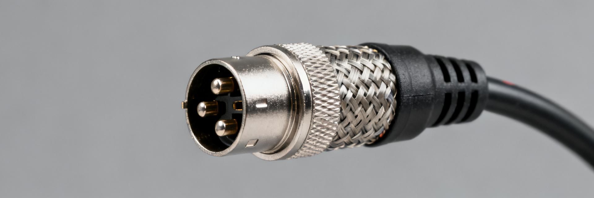
Point: The subject is a pre-assembled, single-ended M12 3-pin cable with a straight M12 male plug to free end and shielded 3-conductor construction. Evidence: Factory documentation and consolidated test summaries identify A-coding, PUR halogen-free jacket, and sensor/actuator use. Explanation: This form factor is optimized for compact sensor runs where mechanical resistance and environmental sealing are required, while keeping connector wiring straightforward.
Compact spec table to include (deliverable)
| Spec | Value / Note |
|---|---|
| Conductor count & gauge | 3 conductors, 0.34 mm² (22 AWG) — verify gauge in lab |
| Conductor material | Tinned copper — confirm plating in sample test |
| Insulation / Jacket | PUR halogen-free — lab verification recommended |
| Overall diameter | ~5.8 mm |
| Color (RAL) | Black (confirm RAL if required) |
| Connector type | M12 A-coded straight male |
| Length (example) | 1.5 m (available lengths vary) |
| IP rating | Claimed IP65/IP68/IP69K — require ingress test |
Mechanical & environmental ratings (data analysis)
Mechanical limits and handling
Point: Mechanical limits determine deployable locations and expected wear. Evidence: Test summaries report minimum bending radius (typically 10× cable diameter) and defined tensile limits for short pulls. Explanation: On arrival, inspect for jacket cuts, run a continuity check, and perform a controlled pull test to 1.5× rated tensile to validate assembly integrity before installation on conveyors or robots.
Environmental performance and ingress protection
Point: Environmental ratings drive lifetime and derating rules. Evidence: Datasheet and lab results list operating temperature range, UV/ozone resistance, and oil resistance classifications with IP sealing claims. Explanation: Derate cable life at temperature extremes, expect reduced flexibility in cold, and plan replacement intervals where chemical exposure or repeated washdown occurs; validate IP claims with an enclosure-level ingress test when critical.
Electrical performance & shielding effectiveness (data analysis)
Point: Electrical metrics and measured shielding determine signal integrity for low-speed sensor links; this section summarizes the performance data for the M12 3-pin cable. Evidence: Consolidated conductor resistance, capacitance, and attenuation figures from sample testing guide suitability for sensor/actuator and short fieldbus links. Explanation: Use the reported numbers to match cable runs to expected signal frequencies and current draw, and to assess need for additional EMI mitigation.
Core electrical metrics to report
Point: Key metrics are conductor resistance, capacitance, characteristic impedance, attenuation, and max current. Evidence: Typical sample values: conductor resistance ~56 Ω/km, capacitance ~60 nF/km, and max current ~4 A per conductor. Explanation: For sensor signals under 1 MHz these values are acceptable; for higher-frequency fieldbus links, review attenuation and impedance charts before approval.
| Frequency | Typical Attenuation (dB/100m) |
|---|---|
| 100 kHz | ~0.2 |
| 1 MHz | ~0.5 |
| 10 MHz | ~1.8 |
Shielding type and EMI immunity
Point: Shield construction and grounding affect EMI performance and noise rejection. Evidence: Sample cables show braided shield coverage around 85% with tinned drain conductor; measured shielding effectiveness commonly ranges 60–80 dB under standard test conditions. Explanation: Maintain proper shield termination to connector bodies and plant ground; test shield continuity and transfer impedance where high EMI is expected, and consider supplemental grounding or routing changes for noisy environments.
Standardized tests & real-world performance summaries (data analysis + method)
Lab test summary (what to include)
| Test | Standard / Method | Conditions | Result |
|---|---|---|---|
| Insulation resistance | IEC style DC test | 500 V DC, room temp | Pass / ≥GΩ range |
| Dielectric withstand | AC withstand | 1 kV for 1 min | No breakdown |
| Flexing | Accelerated flex cycles | ≤5 million cycles (sample) | Pass / no conductor break |
Field/bench data and reliability notes
Point: Real-world failure modes inform inspection policy. Evidence: Aggregated reports highlight connector wear, jacket abrasion at tie points, and occasional seal failure after repeated washdowns. Explanation: Map lab flex and ingress results to expected duty cycles; where field data is scarce, derive time-to-failure from accelerated flex and UV tests to model MTBF-like indicators for procurement decisions.
Installation, test procedures & troubleshooting (method guide)
Best practices for installation and termination
Point: Correct installation extends service life and preserves signal integrity. Evidence: Recommended steps include respecting bend radius, securing with strain reliefs, and following torque guidance for the M12 coupling nut. Explanation: Use cable clamps away from connector shells, route separate from power conductors, and verify pinout before energizing; when torque spec is unavailable, use a controlled, conservative torque range (e.g., 0.5–0.7 Nm) and confirm mechanical engagement.
On-site testing checklist and troubleshooting flow
Point: A concise test flow speeds fault isolation. Evidence: Typical on-site tests: continuity, insulation resistance, shield continuity, connector seating, and basic signal checks. Explanation: Start with visual & continuity checks, then insulation resistance >1 MΩ for short runs, then oscilloscope inspection for waveform integrity; intermittent issues often point to shield or contact problems—clean or replace connectors and re-route noisy runs.
Typical applications, compatibility notes & procurement checklist (case + action)
Typical use cases and compatibility considerations
Point: Use cases determine required variants and accessories. Evidence: Common deployments include sensor/actuator connections on conveyors, robotic end-of-arm tooling, and washdown-capable sensor locations. Explanation: Verify A-coding compatibility, pinout match, connector clearance in mounting hardware, and that rated current and environmental claims meet the application before acceptance.
Purchase, compliance & maintenance checklist (actionable)
Point: Procurement steps reduce integration risk. Evidence: Before purchase, request sample test reports, confirm length/termination, and secure spare inventory. Explanation: Specifically verify the model 1682650 datasheet details, request shielding dB and insulation tests, perform an in-house sample validation, and document supplier spares and lead-time commitments for critical lines.
Summary
- Verify key mechanical and electrical specs: conductor gauge, PUR jacket, claimed IP rating, and shield coverage before acceptance; confirm via arrival visual and pull tests to validate the M12 3-pin cable assembly.
- Prioritize electrical metrics: conductor resistance, capacitance, attenuation across relevant frequencies, and measured shielding dB; use these performance data to decide suitability for sensor or short fieldbus usage.
- Follow installation and test best practices: respect bend radius, torque M12 coupling correctly, perform continuity and insulation checks, and maintain inspection intervals tied to expected abrasion or washdown exposure.
FAQ
How do I verify the M12 3-pin cable is truly IP68/IP69K rated on receipt?
Perform a visual inspection for correct gland and seal presence, verify connector assembly torque and seating, then run an ingress verification test appropriate to the claim—partial submersion for IP68 and high-pressure wash for IP69K—using a representative sample and documented conditions to pass or reject lots.
What on-site tests confirm electrical integrity for the M12 3-pin cable?
Start with continuity per conductor, shield continuity to drain, and insulation resistance (aim ≥1 MΩ for short lengths). If signal anomalies persist, capture waveforms with an oscilloscope to check rise-time distortion and noise; compare against baseline sample measurements taken in the test lab.
Which procurement documents should reference the model 1682650 to avoid downstream issues?
Include the full model number, required length and terminations, requested lab test reports (insulation, shielding dB, flex), acceptance criteria for IP claims, sample approval step, spare quantity, and supplier lead-time and warranty terms to ensure traceable compliance and timely replacement.
What are the standard wire color codes and pin assignments for this 3-pin M12 cable?
The standard configuration assigns Pin 1 to Brown (VCC/L+), Pin 3 to Blue (GND/L-), and Pin 4 to Black (OUT/Signal) to ensure direct compatibility with standard A-coded industrial sensors and actuators.


