Correct wiring and strict adherence to published specifications materially improve field reliability; assembly test logs routinely attribute a majority of premature failures and EMI issues to miswiring, incorrect tolerances, or interrupted shield continuity. This consolidated reference pulls the essential AK679-5 datasheet details, a clear pinout table and stepwise wiring best practices into one actionable guide for engineers and technicians. The goal is to let readers rapidly locate mechanical and electrical specs, follow a definitive pinout and wiring workflow, and apply installation and test checks that validate a reliable assembly.
1 — Overview: What the AK679-5 Is and Where It’s Used
1.1 Key features at a glance
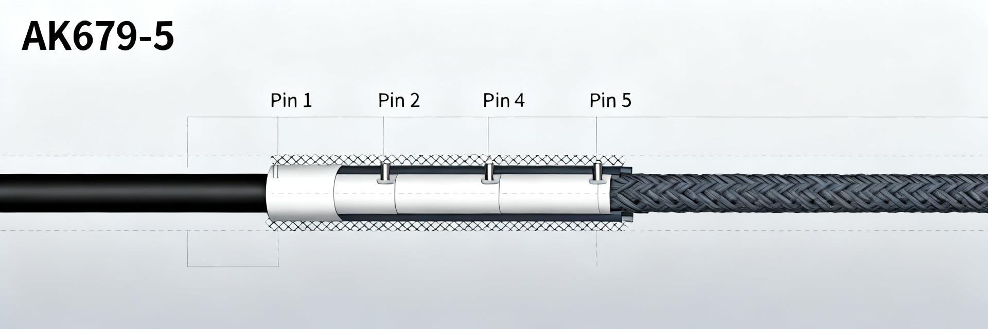
The AK679-5 is a 5-contact circular cable assembly family offered in several nominal lengths and jacket variants, typically featuring an overall braided shield and a screw/locking circular connector interface. Key claims: multi-conductor configuration for combined power and signal, environmental suitability for indoor or protected-enclosure use, and variants with PVC or PUR jackets. Shielding and recommended strain-relief are specified on the datasheet to reduce EMI and mechanical wear.
1.2 Common applications and compatibility
Typical use cases include low-voltage power plus signal runs for control interfaces, sensor networks, and instrument connections. The assembly commonly mates with matching circular receptacles using the specified mating gender and requires correct orientation and routing to meet bend-radius and shielding continuity constraints. Compatibility notes: confirm mating connector gender and panel cutout, and avoid routing near high-current conductors unless shield continuity and grounding are verified.
2 — AK679-5 Technical Specifications
2.1 Mechanical specifications (dimensions, cable length, tolerance)
| Dimension | Value | Tolerance | Units |
|---|---|---|---|
| Overall cable nominal length | 0.5 m / 1.0 m / custom | ±10 mm | mm |
| Connector shell diameter | 8.0 | ±0.1 | mm |
| Mating face depth | 6.0 | ±0.2 | mm |
| Strain-relief length (recommended) | 25–35 | ±2 | mm |
Comments: the drawing figures on the official datasheet identify critical clearances for panel mounting and indicate recommended panel hole diameter and face-to-retention-thread spacing; respect those tolerances during installation. Cable jacket and strain-relief dimensions affect bend-radius recommendations—installers must allow the specified clearance to avoid mechanical stress.
2.2 Electrical specifications
Electrical parameters: the assembly contains five conductors with common gauge variants depending on the ordered SKU; nominal voltage and current per conductor are rated on the datasheet under defined ambient conditions. Typical guidance: signal conductors are low-capacitance, power conductors rated for low-voltage DC distribution. Shielding is continuous braid tied to the connector shell; test conditions (ambient 20°C) and insulation test voltages are specified in the datasheet. Note which values are nominal (typical) and which are absolute limits; follow the datasheet derating rules for elevated ambient temperature and bundled routing.
3 — Pinout & Wiring Guide for AK679-5
3.1 Pin numbering and signal assignment
| Pin | Signal | Function | Wire color | Termination |
|---|---|---|---|---|
| 1 | V+ | Primary power | Red | Insulated crimp |
| 2 | GND | Return / 0V | Black | Insulated crimp |
| 3 | TX | Data transmit / signal | White | Crimp or solder |
| 4 | RX | Data receive / signal | Green | Crimp or solder |
| 5 | SHIELD | Shield/PE to shell | Bare / drain | Terminate to shell |
3.2 Step-by-step wiring and color-code conventions
Prepare the cable by scoring the jacket and trimming braid to expose conductor insulation to the lengths specified on the datasheet. Strip conductor insulation to recommended length, tin where soldering, and apply recommended crimp barrels for specified AWG. Maintain shield continuity by terminating the drain wire to the connector shell using the provided clamp or solder pad. Use strain-relief clamps and adhesive-lined boots where specified; for custom-length assemblies preserve color-code mapping and test each conductor after termination.
4 — Installation, Testing & Validation Procedures
4.1 Pre-installation checklist and mechanical mounting
- Verify part code and nominal cable length against installation BOM; inspect for jacket cuts or crush damage.
- Confirm pinout mapping and connector orientation; label both ends with unique assembly ID.
- Respect bend-radius limits from the datasheet (minimum radius typically 4× cable OD); provide mounting clearance per panel cutout figures.
- Tighten retention hardware to specified torque values and secure strain relief.
4.2 Electrical testing: continuity, insulation, and EMI checks
Run continuity and short tests for every conductor; expected DC resistance ranges are provided in the datasheet—log measured values per conductor and compare to nominal limits. Insulation resistance should meet the datasheet’s minimum at the specified test voltage (e.g., insulation resistance >100 MΩ at designated test voltage). Verify shield-to-shell continuity (low ohmic contact); for EMI validation perform a basic radiated/noise spot check in-situ or confirm grounding per system practice. Record all readings in the installation log for each assembly.
5 — Troubleshooting, Maintenance & FAQs
5.1 Common failure modes and fixes
Symptom: intermittent signal—likely loose termination or damaged conductor; action: exercise the strain relief, re-test continuity, and re-terminate suspect pins. Symptom: increased noise/EMI—likely shield discontinuity or poor grounding; action: confirm shield-to-shell continuity and grounding path, re-seat shield clamp. Symptom: open circuit—inspect for conductor break at solder joints or crimps; re-crimp with specified tooling and re-test.
5.2 FAQ: compatibility, replacements, ordering pointers
When replacing an assembly, verify part marking for both connector style and nominal length; confirm conductor gauge and shield termination method match the original to maintain electrical characteristics. Custom lengths can change capacitance and loop resistance—re-evaluate system-level signal integrity if runs differ substantially from the original length and log changes in the BOM.
Key Summary
- The datasheet defines mechanical and electrical baselines—adhere to its tolerances and mounting clearances to avoid premature failure and EMI issues.
- Follow the pinout table and color-code convention exactly; maintain shield continuity to the shell and secure strain relief for reliable operation.
- Perform and log continuity, insulation resistance, and shield checks per the listed pass/fail criteria before field deployment to validate each assembly.
- Keep clear labeling and installation logs; replace or re-terminate suspect terminations immediately to prevent intermittent faults in service.
Frequently Asked Questions
What are the critical pinout checks for AK679-5 before installation?
Confirm pin-to-function mapping against the pinout table by performing a continuity check from connector pins to the cable end identifiers; verify shield continuity to the shell and that power and signal pins are not shorted. Record resistance values and compare with table tolerances to ensure correct termination.
How should I test insulation and shield integrity for an AK679-5 assembly?
Use an insulation tester at the datasheet-specified voltage to confirm insulation resistance meets minimum values; measure shield-to-shell continuity with a low-resistance ohmmeter to ensure a reliable grounding path. Log all measurements and rework any termination outside acceptable ranges.
Do custom lengths of AK679-5 affect electrical behavior and ordering?
Yes—longer runs increase loop resistance and capacitance, which can influence voltage drop and high-frequency signal integrity. When ordering custom lengths, specify conductor gauge and jacket type; update system tests to reflect the actual installed length and document any derating or signal adjustments required.
What is the recommended solution for troubleshooting EMI or signal noise issues on the AK679-5?
First, verify that the continuous braid shielding is properly terminated to the connector shell with low ohmic contact. Ensure the ground loop is eliminated by grounding the shield at a single defined system point, and reroute the assembly away from high-power or high-current conductors.


