The AK678-2 is presented as a compact, 6-contact circular interconnect widely used in legacy AV, control and instrumentation harnesses; its small form factor and shielding options make it a common choice where space and EMI control matter. This article compiles a practical, data-driven datasheet walkthrough and actionable guidance for engineers and technicians planning procurement, inspection and deployment. The overview balances electrical and mechanical detail with checklists suited for US engineering teams.
Product overview — AK678-2 Mini-DIN 6-pin at a glance
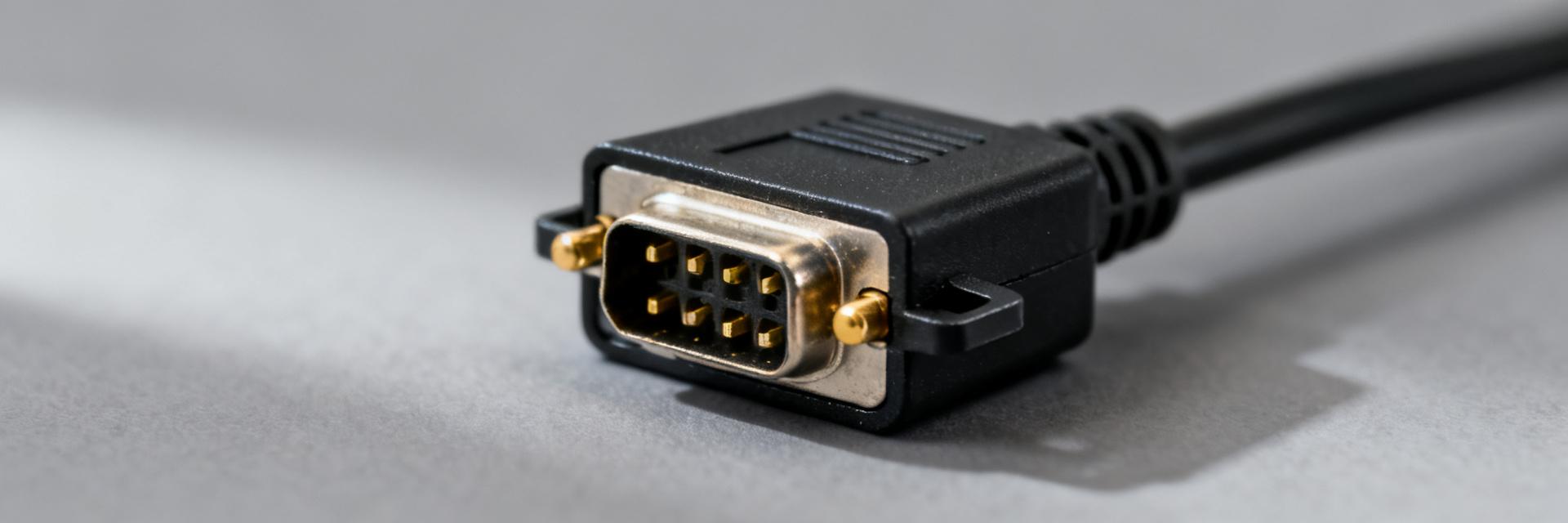
What the AK678-2 is and where it's used
Point: The AK678-2 is a circular 6-contact connector in the Mini-DIN 6-pin family, typically supplied as a molded cable plug or panel receptacle. Evidence: It is used on short runs for single-ended audio/video, control signals and retrofit harnesses on legacy consoles. Explanation: Expect 6 signal contacts, compact 9–13 mm plug OD, and compatibility with common Mini-DIN mating profiles when tolerances match; confirm gender and pin mapping before installation.
Quick spec snapshot (one-line summary table)
Point: Key specs at a glance to support quick procurement decisions. Evidence & Explanation: See the one-line table below for the essential attributes that will be expanded in the full datasheet sections.
| Feature | Value |
|---|---|
| Pin count & arrangement | 6 pins, circular pattern |
| Cable options | Shielded 24–28 AWG, lengths 0.3–10 m |
| Shielding | Braided + foil, drain conductor |
| Connector termination | Molded solder/crimp plug or panel receptacle |
Complete electrical & mechanical specifications
Electrical specifications to check (pinout, voltage/current, impedance, shielding)
Point: Verify pin roles, ratings and SI-relevant numbers before acceptance. Evidence: Typical Mini-DIN 6-pin assemblies assign 1–2 grounds/drain, with remaining pins for signals; rated voltage commonly 30 V DC and rated current 1–2 A per contact, contact resistance ≤30 mΩ, insulation resistance ≥100 MΩ. Explanation: Shielding (braid + foil) reduces EMI and ground loop susceptibility; confirm impedance for any high-frequency signals and flag parameters that affect signal integrity for long runs or mixed-signal harnesses.
| Pin | Typical role |
|---|---|
| 1 | Signal A |
| 2 | Signal B |
| 3 | Ground/Drain |
| 4 | Signal C |
| 5 | Signal D |
| 6 | Shield return / optional power |
Mechanical & material specs (dimensions, tolerance, contacts, cable & termination)
Point: Mechanical tolerances determine interchangeability and durability. Evidence: Expect plug OD in the 9–13 mm range, mating depth 8–12 mm, pin pitch defined for 6-contact Mini-DIN layouts, contact plating typically gold over nickel, insulator thermoplastic. Explanation: Critical tolerances ±0.1–0.2 mm affect mating; specified mating cycles often 500–1,000 cycles, recommended bend radius 4× cable OD, tensile hold >10 N on molded assemblies—confirm these values on the manufacturer datasheet when replacing parts.
How to read the AK678-2 datasheet (step-by-step)
Interpreting drawings, tables and pinout diagrams
Point: Mechanical drawings and pinout charts are the primary sources for fit and wiring. Evidence: Drawings include orthogonal views with units (mm), tolerance blocks, and exploded views showing sealing and strain relief; pinout diagrams label contacts numerically and by signal name. Explanation: Verify view orientation, mating axis, and keyed features; confirm that the panel cutout and mating depth match your installation and that pin numbering convention aligns with your wiring harness documentation.
Key test and environmental parameters to prioritize
Point: Prioritize tests that directly affect reliability in the intended environment. Evidence: Critical datasheet entries include operating temperature range (e.g., −20 to +70°C), humidity/condensation tolerance, dielectric strength (e.g., 500 V AC), and mechanical shock/vibration ratings. Explanation: For consumer AV, focus on continuity and contact resistance; for industrial control, insist on thermal and vibration results meeting application thresholds and require insulation/dielectric test values for procurement QA.
Real-world compatibility & application examples
Typical application scenarios and wiring notes
Point: The connector supports multiple legacy interconnect roles. Evidence: Common uses include single-ended audio/video patching, control signal harnesses for consoles and broadcast racks, and retrofit interfaces on instrumentation. Explanation: For best EMI performance, terminate braid to connector shell or drain conductor at one end; choose plug gender to match panel orientation and allow adapters where signal mapping differs between legacy equipment.
Compatibility checklist with mating parts and cable assemblies
Point: Confirm mechanical and electrical match before ordering. Evidence: Verify pin mapping, cable OD vs. receptacle entry, termination type (solder vs. crimp), contact plating, and shell keying. Explanation: When spec sheets lack detail, request sample mating checks, dimensional prints or measured samples; use continuity checks on sample assemblies to confirm pin-to-pin mapping and mechanical fit before full purchase.
Procurement, inspection and deployment checklist (actionable)
Pre-purchase checklist
Point: A concise procurement checklist prevents wrong-part buys. Evidence: Confirm exact part code, connector gender, cable length, termination style, shield type and contact plating; cross-check electrical ratings, environmental limits and mechanical dimensions on the supplier datasheet. Explanation: Use this as a copy-paste checklist for purchasing: part code, gender, pin mapping, cable AWG & construction, shielding method, contact finish, rated voltage/current, mechanical drawing sign-off, sample availability.
Incoming inspection and field testing procedures
Point: Simple tests catch the majority of assembly defects. Evidence: Recommended acceptance steps: visual check for molding defects, dimensional verification with calipers, continuity and short tests with a multimeter, basic signal verification using a bench source and oscilloscope, and sample tensile/bend checks. Explanation: Pass criteria: continuity <1 Ω where expected, no shorts, contact resistance per spec, and secure shield termination. Common fixes: re-terminate crimp pins, re-seat shell or replace cable end if strain relief failed.
Summary
This guide provides a concise, actionable datasheet walkthrough for the AK678-2 and its Mini-DIN 6-pin form factor, consolidating electrical and mechanical specs, interpretation guidance, compatibility checks and procurement/inspection procedures. Engineers gain a checklist-driven approach to verify pin mapping, ratings and mechanical fit before deployment, together with low-cost field tests to catch common failures and preserve signal integrity across legacy AV and control applications.
- Confirm pin mapping and mating depth against the datasheet before ordering to ensure mechanical and electrical interchangeability for Mini-DIN 6-pin installations.
- Prioritize contact resistance, insulation resistance and shielding type for signal-integrity-sensitive runs; require dielectric/thermal limits for industrial use.
- Use the pre-purchase checklist to capture exact part code, gender, cable AWG, termination and shielding; sample mating and continuity checks prevent most field issues.
Frequently Asked Questions
What should I verify in the datasheet for Mini-DIN 6-pin mating compatibility?
Verify mechanical dimensions (plug OD, mating depth, panel cutout), pin numbering convention, and tolerance blocks; check recommended bend radius and connector keying. Cross-check electrical ratings and shield termination details in the datasheet to confirm the part will mate and function reliably with existing assemblies.
How can I use the datasheet to choose the right cable construction?
Match conductor gauge to the rated current per pin from the datasheet, select shielding (braid+foil) if EMI is a concern, and confirm overall cable OD fits the connector entry. The datasheet should list compatible cable constructions and recommended lengths for maintained signal performance.
What are low-cost incoming inspection tests recommended in the datasheet?
Perform visual inspection, dimensional spot-checks with calipers, continuity and short tests with a multimeter, and a basic functional signal test with a bench source. The datasheet’s contact resistance and dielectric values provide pass/fail thresholds for acceptance testing.


