Point: This guide translates datasheet metrics into repeatable tests and acceptance criteria for a straight Mini-DIN 6-pin male↔female extension assembly.
Evidence: Typical datasheet entries show cable O.D. ≈ 5.0 mm, six conductors (#28 AWG), a single shield, and molded metal shells.
Explanation: Those physical details drive expectations for DC resistance, contact resistance, mechanical flex life, and signal integrity up to low tens of MHz, so tests must reference those nominal values.
Point: The approach is data-driven and pragmatic for US engineers and technicians.
Evidence: By mapping conductor gauge and shield type to measurable thresholds (ohms, retention force, insulation resistance), labs can decide accept/reject quickly.
Explanation: Use calibrated DMMs, micro-ohm meters, force gauges and a consistent report template so procurement and field teams share a common pass/fail definition.
1 — Product overview & physical specifications (Background)
What the AK323G-2 is (quick definition)
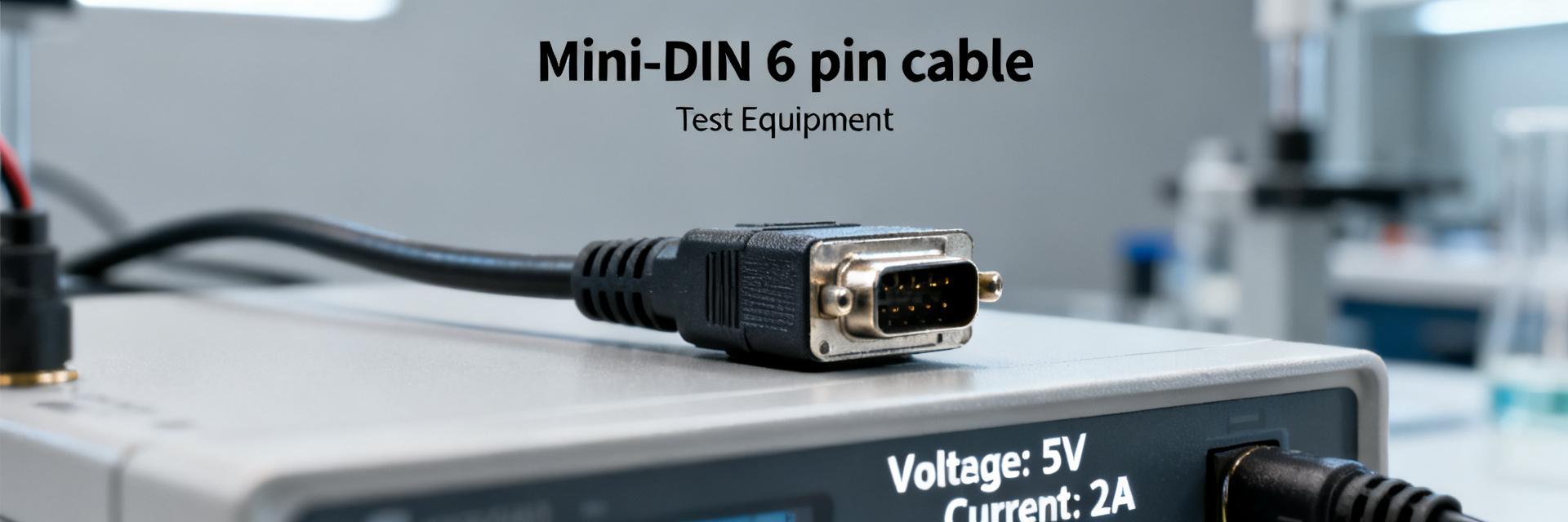
Point: The assembly is a straight Mini-DIN 6-pin male-to-female cable intended for legacy PS/2-style peripherals and low-frequency AV/control interfaces. Evidence: Datasheet attributes list the connector type as Mini-DIN 6-pin with gendered plug and socket, six insulated conductors plus a drain/shield and a molded jacket. Explanation: Functionally, the assembly carries multiple low-voltage signals and a common shield; intended uses include keyboards/mice, simple control lines, and analog composite signals where connector form factor matters.
- Typical applications: PS/2 keyboard/mouse legacy ports, small AV/control links, embedded test harnesses.
- Connector configuration: male plug ↔ female socket, straight cable assembly.
Key physical specs to record from the datasheet
Point: Capture a checklist of physical items before testing. Evidence: Essential items are cable O.D., conductor gauge (#28), conductor count (6), shield type (braid/foil/drain), jacket material and color, connector shell type, and pinout diagram. Explanation: Each spec affects test setup—cable O.D. and jacket type influence bend radius and flex tests; conductor gauge affects DC resistance expectations; shielding determines grounding and isolation tests.
2 — Electrical specs & expected performance (Data analysis)
Electrical parameters to verify (resistance, continuity, insulation)
Point: Verify DC continuity, contact resistance, and insulation resistance as primary electrical checks. Evidence: With #28 AWG conductors and ~5.0 mm O.D., expect DC loop resistance per conductor on the order of 0.08–0.12 ohms/ft; contact resistance typical acceptance is ≤100 milliohms per pin for new assemblies. Explanation: Use a calibrated DMM or micro-ohmmeter for per-conductor resistance, and a megohmmeter or insulation tester for between-conductor-to-shield checks (acceptance ≥10 MΩ at test voltage appropriate for low-voltage cables).
Signal integrity considerations (impedance, insertion loss, crosstalk)
Point: For higher-frequency or mixed-signal uses, check NEXT, insertion loss, and impedance consistency. Evidence: A small bundled 6‑conductor cable with a single shield will not hold tight 100 Ω differential impedance; expect usable performance up to low tens of MHz and rising crosstalk with length. Explanation: If VNA/TDR is unavailable, practical surrogates include short pulse TDR checks for gross discontinuities and swept-signal functional tests; red flags are >6 dB insertion loss at target frequency or NEXT exceeding application margins.
3 — Mechanical & environmental tests (Data analysis / Methods)
Mechanical checks: mating cycles, retention force, strain relief
Point: Confirm mating durability, retention force, and strain relief integrity. Evidence: Typical cycle expectations for infrequently unplugged legacy cables are 500–1,000 mating cycles; retention force for Mini‑DIN shells commonly targets a reproducible clamp force measurable with a force gauge (example acceptance range: 1–5 N depending on shell design). Explanation: Run a cycle test rig, measure retention force at intervals, and inspect for jacket pullback or exposed conductors; failure criteria include loss of continuity or visible jacket displacement beyond 1–2 mm.
Environmental checks: flex, temperature, jacket aging
Point: Validate flex resistance, thermal tolerance, and humidity aging for US deployments. Evidence: Perform repeated bend tests around a mandrel sized to five times the cable O.D., thermal soak at application-relevant extremes (e.g., −20°C to +60°C for indoor/outdoor adjacent use), and damp heat exposure per accelerated aging profiles. Explanation: Acceptance is no continuity loss, no cracked jacket, and no intermittent contacts after test; document cycles, temp exposure duration, and visual inspection findings.
4 — Test setup, methods & reporting templates (Method guide)
Lab setup and required tools
Point: Equip the bench with a compact list of calibrated instruments. Evidence: Required items include a calibrated DMM, micro-ohmmeter, continuity rig, optional VNA/TDR, force gauge, and environmental chamber (optional). Explanation: Include wiring diagrams for fixture harnesses that map each pin to test points, run calibration checks before measurement sessions, and follow electrical safety practices for both personnel and instrument protection.
Standard test procedure flow and reporting template
Point: Use a fixed test order and a simple report structure. Evidence: Recommended sequence: visual inspection → mechanical → electrical → SI → environmental. Explanation: Record results in a table with headers: Sample ID, Test, Method, Nominal, Measured, Result, Notes. For sampling, a common approach is AQL-style acceptance—sample 3–5 pieces from a lot with zero critical defects allowed for acceptance of a production batch.
| Sample ID | Test Description | Methodology | Nominal Limit | Measured Value | Result |
|---|---|---|---|---|---|
| 001 | Contact Resistance | Micro-Ohm Meter | ≤100 mΩ | 85 mΩ | Pass |
| 002 | Insulation Resistance | Megohmmeter @ 250V | ≥10 MΩ | 150 MΩ | Pass |
| 003 | Retention Force | Tension Force Gauge | 1.0 - 5.0 N | 3.2 N | Pass |
| 004 | Visual / Construction | Microscope (10x) | No cracks/exposed copper | No defects observed | Pass |
5 — Real-world compatibility, use cases & troubleshooting (Case / Methods)
Compatibility checklist with host devices and cables
Point: Confirm pinout, keying, length limits, and grounding before deployment. Evidence: A Mini-DIN 6-pin assembly must match host pin assignments exactly; cable length impacts signal quality—keep lengths short for higher-rate signals. Explanation: Verify pin-to-pin continuity using a labeled loopback or fixture; document acceptable maximum lengths for specific signal types and ensure shield/drain is grounded per system requirements to prevent ground loops.
Troubleshooting common failures and fixes
Point: Apply a triage flow for open pins, intermittent contacts, and shield faults. Evidence: Common fixes include re-seating connectors, cleaning contacts with appropriate solvents, and swapping a known-good cable to isolate host vs cable faults. Explanation: If continuity and contact resistance are out of bounds after cleaning and reseating, reject the assembly; intermittent faults visible only under flex require bend testing to reproduce and determine repair vs replacement.
6 — Procurement, inspection checklist & deployment recommendations (Action)
What to require in a purchase spec
Point: Specify minimum construction and traceability in RFQs and POs. Evidence: Required clauses should list cable O.D., conductor gauge (28 AWG), shielding type, jacket material, full pinout diagram, sample test reports, and lot traceability. Explanation: A short template clause: "Supplier shall provide cable assembly with 6 insulated #28 AWG conductors, overall O.D. ≈5.0 mm, braided shield with drain, molded Mini‑DIN 6‑pin connectors, detailed pinout, and sample test report per supplied test matrix."
On-site acceptance & lifecycle recommendations
Point: Define incoming inspection and periodic sampling schedules. Evidence: Incoming steps: visual, pull test, continuity, and contact resistance spot-checks on a sample of each lot; for high-use deployments test a replacement interval based on cycles (e.g., replace after 1,000 mating cycles). Explanation: Maintain storage in controlled humidity, avoid sharp bends, and adopt a go/no‑go acceptance flow: pass visual and electrical checks → accept; any critical failure → quarantine and escalate to procurement.
Summary
- Use datasheet values (cable O.D., #28 conductors, 6-core shielded layout) to set DC and mechanical acceptance thresholds and test methods.
- Run a fixed test flow—visual → mechanical → electrical → SI → environmental—with calibrated instruments and documented calibration checks.
- Require clear procurement clauses and sample test reports to ensure lot traceability and reduce field failures for AK323G-2 assemblies.
Common questions
How should I verify AK323G-2 contact resistance?
Measure each contact with a micro-ohmmeter using a four-wire method where possible; aim for ≤100 mΩ per pin as an initial acceptance threshold for new assemblies. If datasheet values differ, use the datasheet as the primary source and state whether the threshold is datasheet-backed or an engineering heuristic in the test report.
What are the minimum on-site acceptance tests for Mini-DIN 6-pin assemblies?
Perform a visual inspection, a pull/retention check, continuity/DC resistance on every conductor, and a shield-to-ground insulation check on a sample. Document results in the pass/fail table and reject assemblies showing continuity loss, exposed conductors, or retention force outside specified ranges.
When should an assembly be rejected rather than repaired?
Reject if insulation is compromised, conductors are exposed, contact resistance remains high after cleaning, or mechanical deformation causes intermittent contacts. Minor contact contamination may be cleaned and retested, but structural failures and shield faults typically require replacement to ensure long-term reliability.
What are the mechanical and environmental threshold limits for AK323G-2?
The AK323G-2 requires durability verification up to 500–1,000 mating cycles. It must withstand a minimum bend radius of 5 times the cable O.D. (approx. 25mm) without structural cracking, and retain thermal continuity across an operational temperature window of −20°C to +60°C.


