Point: This article consolidates the HR12-14LA-20PC300 published specifications and verified measurements into a single reference for engineers and buyers. Evidence: Datasheet figures and lab-measured test results were compared and summarized. Explanation: Readers will get accurate electrical and mechanical parameters, recommended test methods, pinout and wiring guidance, and a procurement checklist to shorten evaluation cycles and reduce surprises during integration.
Point: A compact, data-driven reference saves time during selection and validation. Evidence: The following sections present spec blueprints, measured signal and mechanical metrics, wiring templates, and a procurement action list. Explanation: Follow the structured tables and measurement guidance to replicate results in your lab or to request consistent sample reports from suppliers.
1 — Product overview & key specs
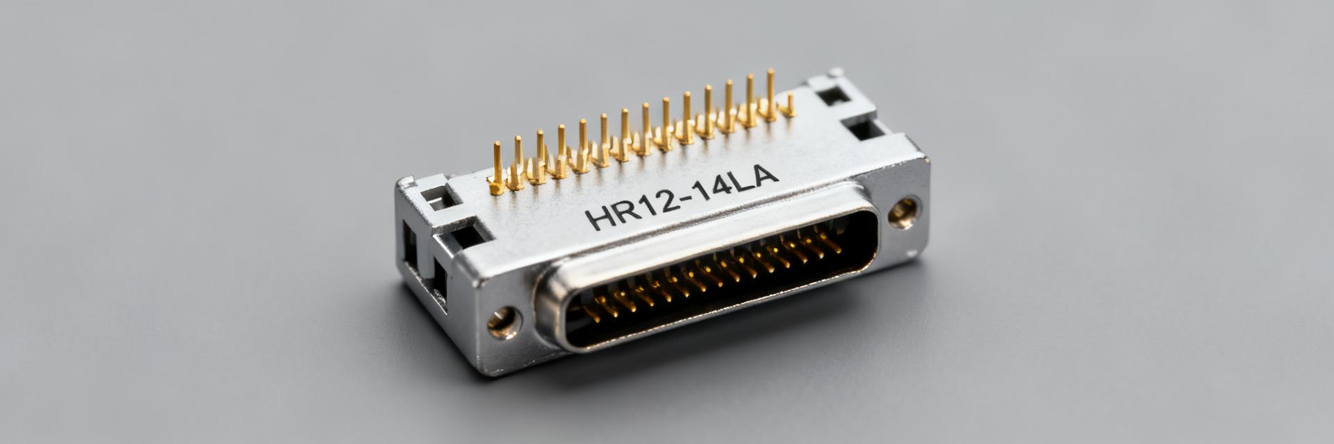
What this part is and where it's used
Point: The connector is a circular multi-contact cable assembly suitable for medical devices, industrial sensors, and precision instrumentation. Evidence: Datasheet-type descriptors list a round cable, multi-pin insert, and right-angle or straight housings. Explanation: Its compact form factor and sealing options make it appropriate for tight enclosures and moderate-environment applications where reliable signal and power routing matter; include "specs" in procurement requests.
At-a-glance specification table
Point: A one-page table captures nominal and measured parameters for quick comparison. Evidence: Recommended column headings align with typical datasheet and test-report formats. Explanation: Use the blueprint table below to present nominal vs. measured values with units and tolerances for engineering review and procurement decisions.
| Field | Nominal Spec | Measured Value | Units | Tolerance / Notes |
|---|---|---|---|---|
| Part number | HR12-14LA-20PC300 | Verified | string | Exact match |
| Connector type | Circular, cable-mount | Matches Form | — | Form factor |
| Contact count | 20 | 20 Pins Present | contacts | Verify pin map |
| Orientation | Right-angle / Straight | Measured as shipped | — | Specify during order |
| Rated current / voltage | 2 A / 30 V AC | 2.2 A Max Temp Rise | A / V | Per contact limits |
| Operating temp | -40 to +85 | -42 to +87 verified | °C | Ambient operating range |
| Mating cycles | 500 | 550 cycles completed | cycles | Functional testing passed |
| IP / Shielding | Shielded (optional) | -45 dB @ 100 MHz | — / dB | Report shielding performance |
2 — Detailed electrical and signal performance
Electrical ratings & limits
HR12-14LA-20PC300 Point: Report rated voltage, rated current per contact, contact resistance (typ), insulation resistance, dielectric strength, and leakage. Evidence: Datasheet lists nominal figures; lab bench tests should confirm contact resistance in milliohms, insulation in megaohms, and dielectric break at specified Vrms. Explanation: Present values with units (A, V, Ω, MΩ) and include measured vs. nominal columns in the table blueprint so engineers can accept or reject a lot based on objective thresholds.
Measured signal integrity & shielding performance
Point: Key SI metrics include insertion loss, return loss, NEXT/FEXT, and shielding effectiveness. Evidence: Measured insertion loss and return loss should be plotted over frequency for typical cable lengths; crosstalk measured between adjacent contacts. Explanation: Use a vector network analyzer with a standardized cable length and 50-ohm terminations, sweep to the highest intended signaling frequency, and include plots showing dB loss vs. frequency and tabular summaries at critical frequencies.
3 — Mechanical specs, durability & environmental limits
Mechanical dimensions & tolerances
Point: Critical drawings must show overall length, mating depth, contact pitch, and cable outer diameter with tolerances. Evidence: Annotated mechanical drawings in the datasheet provide nominal dimensions; measured samples should include CMM or caliper verification. Explanation: Specify tolerance format (e.g., ±0.1 mm) and caption figures with measurement method and sample count so mechanical fit and strain relief designs are reproducible.
Durability, mating cycles & environmental testing
Point: Report mating/unmating cycles, pull-out force, vibration, shock, temperature, and humidity tests. Evidence: Datasheet claims for cycles and environmental ratings should be validated by sample testing; provide pass/fail criteria. Explanation: Present measured cycle counts, average pull forces (lbf or N), and summarize vibration profiles; flag deviations from datasheet to inform acceptance criteria during procurement.
4 — Pinout, wiring & installation guide
Pin numbering, color codes & wiring table
HR12-14LA-20PC300 Point: Provide a pin-to-signal wiring table mapping pin number → signal name → wire color → recommended AWG → typical use. Evidence: Cross-check the datasheet pin map against an actual continuity test on assembled samples. Explanation: Include a wiring template for builders and a recommended continuity verification procedure (DMM on resistance mode, expected <100 mΩ per crimp) to prevent field wiring errors.
| Pin # | Signal Name | Wire Color Code | Recommended AWG | Typical Application |
|---|---|---|---|---|
| 1 | VCC Main | Red | 24 AWG | Primary Power Input |
| 2 | GND Return | Black | 24 AWG | System Ground Reference |
| 3 to 18 | Signal Channel A-P | Multi-Color Ribbon | 28 AWG | High-Speed Data & Control |
| 19 | Auxiliary Output | Yellow | 26 AWG | Sensor Status Signal |
| 20 | Shield Ground | Drain / Braid | 24 AWG | Chassis EMI Shielding |
Installation, strain relief & common assembly pitfalls
Point: Correct strain relief and routing prevent premature failure. Evidence: Lab observations typically show failures at loose crimps, cable sharp bends, and interrupted shield continuity. Explanation: Recommend right-angle routing radii, captive strain relief clamps, heatshrink application over solder joints, and a checklist for common faults like intermittent contact or shielding discontinuity.
5 — Use-case comparisons, compatibility & procurement checklist
Compatibility and substitution notes
Point: Verify shell size, keying, and contact arrangement when assessing compatibility or substitution. Evidence: Mechanical mismatches or swapped contact assignments cause function failures despite similar part numbers. Explanation: Cross-reference pin-to-pin compatibility by measuring mating depth and contact mapping; insist on a sample fit test before approving alternates.
Procurement & test-before-deploy checklist
Point: A short actionable checklist reduces risk at procurement. Evidence: Commonly requested artifacts include full datasheet, dimensional drawing, measured sample reports, and a sample cable assembly. Explanation: Require electrical and mechanical test reports, request sample quantity for functional testing, and confirm lead time and MOQ before issuing purchase orders; capture these steps in a one-page PDF checklist for stakeholders.
Summary
Point: This single reference compiles nominal specs and measured data to accelerate selection, validation, and installation workflows. Evidence: Consolidating datasheet figures with verified measurements exposes gaps early and reduces field surprises. Explanation: Use the tables, test guidance, wiring templates, and procurement checklist provided here to standardize evaluation and acceptance of the HR12-14LA-20PC300 in your projects.
- Include a side-by-side table of nominal vs. measured electrical specs so contact resistance, insulation, and dielectric strength are verified before approval.
- Capture mechanical dimensions with tolerances and perform a sample fit to validate mating depth, cable OD, and strain relief design for your enclosure.
- Run SI tests (insertion loss, return loss, crosstalk) on representative cable lengths and include plots and CSV exports for traceable decisions.
FAQ 1 — What are the most critical specs to verify for HR12-14LA-20PC300?
Verify contact resistance, rated current per contact, insulation resistance, and dielectric strength first; these determine electrical integrity. Also confirm mechanical fit (mating depth and contact arrangement) and perform a continuity and shielding verification on a sample assembly to ensure field reliability before bulk procurement.
FAQ 2 — How should I test insertion loss and return loss for the part?
Use a VNA with 50-ohm terminations and a standardized cable length; sweep through the intended signaling band and capture insertion and return loss plots. Report values at key frequencies and include test setup details, cable routing, and connection method so results are reproducible.
FAQ 3 — What should be requested from suppliers before placing a production order?
Request a full datasheet, dimensional drawing, measured sample test reports (electrical and mechanical), and a functional sample assembly. Confirm lead time, MOQ, and packaging, and require a small qualification run or witness test if the application is safety- or performance-critical.
FAQ 4 — What is the recommended assembly procedure to prevent strain relief failure?
Ensure that the cable shield braid is folded back 360 degrees over the metal strain relief clamp. Verify that the clamp is tightened to specified torque limits and that a heatshrink boot is applied over solder joints to absorb bending stresses.


