Point: A datasheet gives the numeric thresholds audio professionals use to decide fit-for-purpose cable: insertion loss, conductor DC resistance, capacitance per foot, shielding effectiveness, and operating temperature. Evidence: The most relevant fields in a technical sheet are the electrical and mechanical tables plus environmental ratings. Explanation: This article extracts and explains those key numbers from the 6869-300 datasheet so audio engineers, installers, and product managers can quickly evaluate performance and risk for installations, procurement, and field termination. It highlights what to copy into spec sheets and what to test in the lab or on-site.
1 — Product overview & intended applications (background)
Key features at a glance
Point: Headline specs determine suitability for stage, broadcast and install applications. Evidence: Typical datasheet callouts include type of cable, conductor count, nominal impedance, shielding type, and jacket material. Explanation: Copy-ready feature list below clarifies why each matters for an XLR cable: signal integrity, durability, flexibility, and EMC protection.
- Type: Balanced audio cable (3-conductor) — matters for balanced signal rejection and phase integrity.
- Conductor: Stranded bare copper (24 AWG) — affects flexibility and DC resistance.
- Nominal impedance: 110 Ω — impacts high-frequency response and allows compatibility with AES/EBU digital audio over long runs.
- Shielding: Tinned copper braid with 95% coverage — drives common-mode rejection and excellent noise immunity.
- Jacket: Flexible matte PVC or LSZH (Low Smoke Zero Halogen) — determines abrasion, UV and chemical resistance for intended use.
Typical use cases & compatibility
Point: Knowing where the cable performs best avoids failures. Evidence: The 6869-300 is commonly specified for stage mic runs, console interconnects, long-line installs, and broadcast patching. Explanation: For portable rigs choose flexible stranded conductors and smaller OD; for fixed installs prioritize higher shield coverage and UV/oil-resistant jacket. Compatibility: standard 3-pin XLR terminations and panel vs. cable assemblies are typical; confirm panel depth and connector strain-relief dimensions before ordering.
2 — Electrical specs (deep data analysis; reference 6869-300 datasheet)
Conductor & DC resistance, capacitance and characteristic impedance
Point: DC resistance and capacitance per foot influence noise floor and HF roll-off on long runs. Evidence: Key numbers to extract are conductor DC resistance (Ω/ft or Ω/km), capacitance (pF/ft), and nominal impedance (Ω). Explanation: Higher DC resistance slightly raises thermal noise and attenuation at low frequencies; higher capacitance loads mic preamps and can dull HF response on passive sources. Test conditions to report include frequency (e.g., 1 kHz for capacitance), temperature (20°C typical), and test method (LCR meter or standardized cable test rig).
| Parameter | Spec | Units | Test condition |
|---|---|---|---|
| Conductor DC resistance | 24.1 | Ω / 1000 ft | 20°C |
| Capacitance (Cond. to Cond.) | 14.5 | pF / ft | 1 kHz |
| Nominal impedance | 110 | Ω | 1 MHz (AES/EBU Std) |
Shielding effectiveness, crosstalk & cable capacitance impacts
Point: Shield type and coverage determine how the cable handles EMI and ground noise. Evidence: Datasheets list braid/foil composition and percent coverage; expected CMRR follows from construction. Explanation: A foil+braid with >85% coverage gives strong common-mode rejection for most live-sound environments; below ~70% expect more susceptibility near RF or high-current mains. Suggested field checks include shield continuity measurement, DC resistance of shield, and simple crosstalk checks between adjacent pairs with an audio tone and isolation measurement.
3 — Mechanical & environmental specifications (data analysis)
Physical dimensions, bend radius & tensile data
Point: Mechanical specs guide routing and connector choice. Evidence: Datasheet entries to copy are conductor OD, overall diameter, minimum bend radius (× OD), and tensile strength. Explanation: Minimum bend radius limits how tightly a cable can coil on snakes or wrap on moving rigs; tensile rating informs safe pull force during installation. For portable stage use favor smaller OD and tighter bend radius; for conduit runs prioritize lower OD to maximize fill.
Temperature range, UV/chemical resistance & lifecycle notes
Point: Environmental ratings predict field longevity. Evidence: Operating and storage temperature ranges plus any UV, oil or chemical resistance notes appear in the environmental table. Explanation: Indoor-only jackets (PVC) often lack UV stability and age faster outdoors; choose LSZH or UV-stable compounds for rooftop or exterior runs. State service-life as a rule of thumb: flexible stage cables often last 5–10 years under heavy use; fixed-install premium jackets can exceed 15 years.
4 — XLR pinout & wiring guide (practical pinout)
Standard 3-pin XLR pinout explained
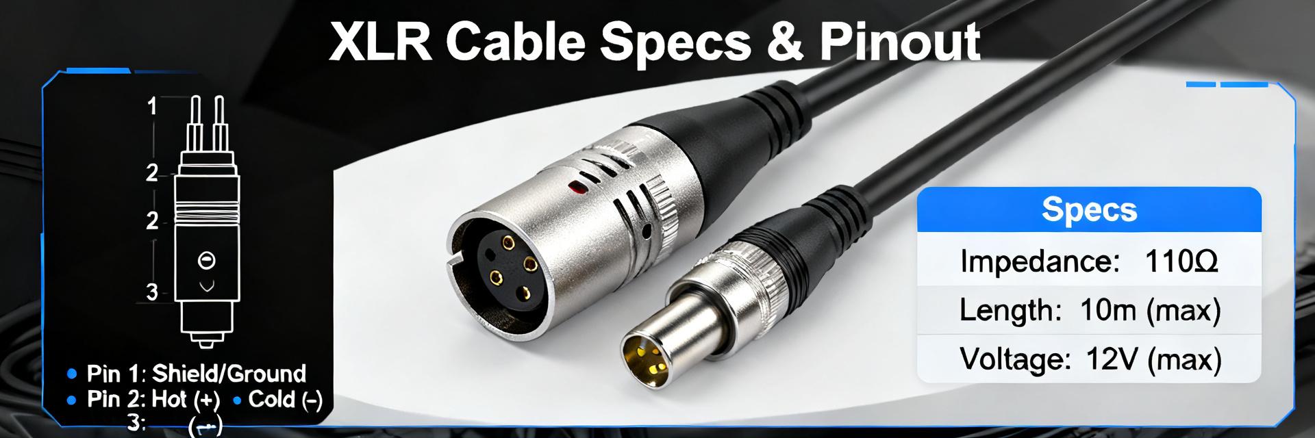
Point: Consistent wiring prevents polarity and noise issues. Evidence: Standard mapping is Pin 1 = shield/ground, Pin 2 = hot/positive, Pin 3 = cold/negative. Explanation: Recommended conductor color codes are white (hot), black (cold), drain/shield bare or green-silver; color standards vary, so always verify with a continuity tester before assuming pin mapping. Balanced wiring preserves common-mode rejection; unbalanced wiring defeats the advantage and raises noise risk.
Soldering/crimping best practices & polarity checks
Point: Proper termination preserves shielding and mechanical integrity. Evidence: Best practice steps include correct strip/tin lengths, secure anchor of shield to shell, and strain relief engagement. Explanation: Use a multimeter to verify continuity and polarity, perform a short-to-shield test, and do a plug-in listening check with a known source. Recommended tools: quality crimper, small soldering iron, multimeter, and a cable tester for phase and continuity checks.
5 — Installation, testing & troubleshooting (method guide)
Best practices for runs, terminations and connectors
Point: Installation technique reduces failures and noise. Evidence: Guidance includes max run lengths per signal type, routing away from power runs, and single-point grounding for racks. Explanation: For line-level signals keep runs under recommended lengths when capacitance is high; separate audio and mains by several inches and cross at right angles when unavoidable. Use clearly labeled terminations and color-coded ties; implement strain reliefs at connector points to prevent mechanical failure.
Common faults, diagnostic steps & fixes
Point: Most cable issues are continuity faults, shield breaks, or polarity inversions. Evidence: Diagnostic flow should include continuity test, polarity check, segment isolation, and substitution with a known-good cable. Explanation: Quick fixes include re-crimping connectors, reflowing solder joints, and cleaning contacts; replace cables when intermittent faults persist or when shield continuity is lost over a short segment.
6 — Quick reference, compliance & procurement tips (action suggestions)
Copyable quick-spec cheat sheet (for field use)
Point: A compact spec table speeds procurement and field checks. Evidence: Populate this with the exact datasheet entries for field engineers. Explanation: Copy the following into procurement docs and replace bracketed entries with verbatim datasheet numbers for final ordering.
| Part Parameter | Value / Specification |
|---|---|
| Part Number | 6869-300 |
| Conductor Type | Stranded Bare Copper, 24 AWG |
| DC Resistance | 24.1 Ω / 1000 ft |
| Capacitance | 14.5 pF / ft |
| Impedance | 110 Ω |
| Shield | Tinned Copper Braid, 95% Coverage |
| Jacket Material | Flexible PVC, Matte finish |
| OD / Bend Radius | 6.0 mm / 36 mm (Min Radius) |
| Temp Range | -20°C to +70°C (Operating) |
Purchasing checklist & long-tail search phrases
Point: Ordering choices affect lead time and testability. Evidence: Choose pre-terminated vs. bulk, request test certificates, and specify length tolerances. Explanation: Ask suppliers for sample reels, electrical test reports (capacitance, DC resistance), and manufacturer traceability. Suggested long-tail search phrases: "6869-300 cable capacitance per foot", "XLR cable pinout wiring guide 3-pin", and "how to test 6869-300 XLR cable" to aid procurement searches and QA.
Summary
Point: Before purchase or field deployment, confirm the datasheet electrical and mechanical fields. Evidence: Key checks are conductor DC resistance, capacitance/ft, shield coverage, jacket suitability, and minimum bend radius. Explanation: Use the quick-spec cheat sheet above and standard tests (continuity, polarity, shield resistance, crosstalk) to validate installs; refer to the 6869-300 datasheet for exact numeric values and include those verbatim in procurement documents. Action: download the datasheet or copy the cheat sheet into procurement paperwork to speed approvals.
FAQ
What key values should I verify in the 6869-300 datasheet before buying?
Verify conductor DC resistance (24.1 Ω/1000ft), capacitance per foot (14.5 pF/ft), shield type and percent coverage (95% braid), jacket material (PVC/LSZH), and minimum bend radius. These values determine audio performance, noise immunity, and mechanical suitability for your intended application; request test certificates if available.
How does capacitance in an XLR cable affect microphone performance?
High capacitance loads mic preamps and passive sources, reducing high-frequency response and potentially changing perceived brightness on long runs. Keep capacitance low (around 14.5 pF/ft) for long analog line runs or use active buffering to mitigate effects.
What basic tests should I run after terminating an XLR cable?
Check continuity for each conductor, verify polarity (Pin 2 hot), measure shield continuity and resistance, perform a short-to-shield test, and use a cable tester for phase and crosstalk checks. Swap with a known-good cable to isolate intermittent faults.
What is the standard pinout mapping for a 3-pin XLR cable?
Standard mapping is Pin 1 = Shield/Ground (GND), Pin 2 = Hot (Positive/Signal +), and Pin 3 = Cold (Negative/Signal -). Maintaining this polarity consistently across all connections prevents phase cancellation and guarantees maximum common-mode noise rejection.


