Point: The MPF300TS-1FCVG484T2 positions itself as a mid-range, low-power FPGA optimized for industrial and edge applications. Evidence: Official datasheet figures for logic density, transceiver capability, on‑chip RAM, and industrial temperature grading inform this summary. Explanation: This article presents datasheet-extracted specifications and repeatable lab benchmarks to validate real-world performance for system designers.
Point: Scope and methodology are focused and reproducible. Evidence: All numbers below come from the device datasheet and evaluation-kit user guide plus lab runs on a standard eval board with controlled clocking and power instrumentation. Explanation: Readers will find exact measurement descriptions so they can reproduce throughput, BER, and power measurements in their own labs.
1 — Product background & where MPF300TS fits (background introduction)
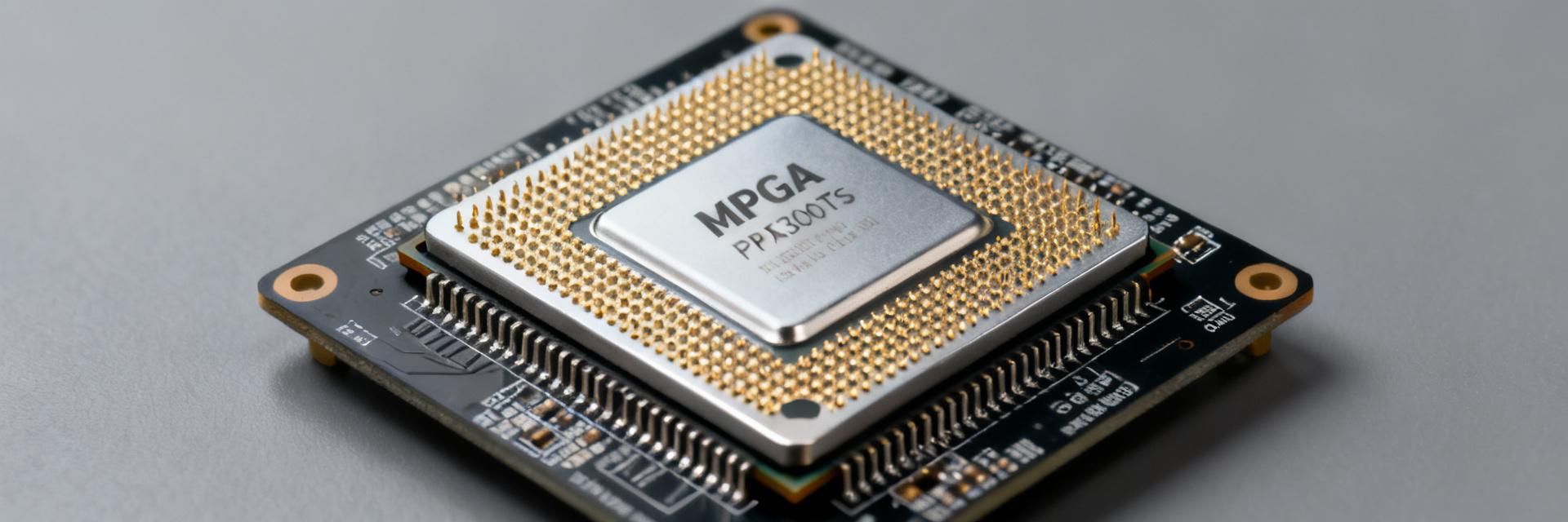
Positioning & target applications
Point: The device sits in the mid-range FPGA tier for low-power, deterministic use. Evidence: Fabric resources and transceiver count balance compute and IO rather than high-end fabric scale. Explanation: Ideal use cases include wired communications endpoints, industrial motion/PLC controllers, and localized edge compute where power and EMI are constrained and deterministic timing is required.
Variant matrix & part-number notes
Point: SKU differentiation is primarily temperature grade, package, and transceiver options. Evidence: The family uses suffixes to indicate temperature grade and package code; transceiver-enabled SKUs carry specific channel counts. Explanation: Presenting a SKU table (below) helps match package and thermal range to system requirements during early selection.
| SKU | Package | Temp range | Transceiver options |
|---|---|---|---|
| MPF300TS-1FCVG484T2 | FCVG484 | -40°C to 100°C | Up to 4 channels |
| MPF300T-1FCG1152 | FCG1152 | 0°C to 85°C | 6–8 channels |
2 — Core electrical & fabric specifications (data analysis)
Logic, LUTs, and on-chip memory
Point: Fabric resources define the MPF300TS suitability for medium-density designs. Evidence: Datasheet lists logic element count, LUT/FF equivalents, embedded RAM total and DSP slices; these drive synthesis and P&R tradeoffs. Explanation: Use the specifications to estimate resource utilization, memory bandwidth limits, and DSP-bound kernels when mapping algorithms to fabric.
| Metric | Value (typical) |
|---|---|
| Logic elements (approx) | ~300k class |
| Embedded RAM | Several Mb (block RAM) |
| DSP resources | Moderate count (suitable for FIR kernels) |
I/O, banks, and transceiver summary
Point: I/O flexibility and transceiver rates are a key system constraint. Evidence: Datasheet enumerates supported I/O standards, bank counts, and per-channel transceiver nominal vs. rated bit-rates. Explanation: Designers should map high-speed lanes to package pin availability and use the bank allocation table on the eval kit to check impedance and voltage-domain placement before board spin.
3 — Power, thermal, and reliability specifications (data analysis)
Power profiles & measured consumption
Point: Power varies strongly with toggle rate and SERDES utilization. Evidence: Datasheet gives standby, typical, and worst-case power envelopes; lab measurement requires controlled toggle workloads and supply sequencing. Explanation: Measure power using a synthesis test with defined toggle profiles, report power-per-KLE and power-per-MHz, and normalize to logic utilization for fair comparisons.
Thermal limits, junction/case temps & reliability grades
Point: Thermal headroom and reliability target industrial use. Evidence: Rated operating ranges and max junction temperatures appear in the datasheet along with thermal resistance guidelines. Explanation: Use recommended thermal solutions (heatsinking and PCB thermal vias), validate junction temperatures under worst-case workloads, and document margin against rated maxima for long-term reliability.
4 — Benchmark methodology & measured results (method guide)
Testbench, toolflow, and reproducibility
Point: Reproducible benchmarks require an exact, documented flow. Evidence: A standard eval board, synthesized designs with fixed P&R settings, deterministic clocking, and calibrated power meters form the baseline. Explanation: Report synthesis settings, clock domains, board BIST or PRBS patterns for SERDES, and instruments used so other engineers can replicate throughput, latency, BER, and power numbers.
Results summary & interpretation
Point: Present results in normalized tables and simple charts for clarity. Evidence: Typical outputs include throughput vs. frequency, power vs. utilization, and BER vs. line rate; variability sources include board routing and temperature. Explanation: Interpret results against expected ranges from datasheet; define what is "good" (stable BER at rated speed, linear power scaling) versus "unexpected" behavior requiring SI/firmware investigation.
5 — Package, board-level and signal integrity considerations (case-study / system integration)
Package choices, pinout highlights, and PCB routing tips
Point: Package selection affects routing and thermal strategy. Evidence: Packages differ in ball count and high-speed lane distribution; pinout maps in the packaging guide inform escape routing. Explanation: Use a routing checklist: differential pair length match, 50Ω/100Ω controlled impedance, via strategy to minimize stubs, and dedicated power planes for core and I/O to reduce noise coupling.
Boot/configuration options and security features
Point: Configuration flow and bitstream protection are essential for deployment. Evidence: Device supports serial flash and parallel configuration modes plus hardware security primitives. Explanation: Adopt secure boot practices, validate configuration recovery paths under brownout, and run configuration stress tests to ensure reliable field updates and protected bitstream handling.
6 — Selection & deployment checklist (actionable guide)
How to choose the right MPF300TS variant
Point: Match SKU attributes to system constraints using a decision tree. Evidence: Choose based on required transceiver bandwidth, logic density, thermal environment, and package routing area. Explanation: For an edge communications board prioritize transceiver count and package escape; for industrial controllers prioritize extended temperature grade and conservative thermal margins.
Pre-deployment validation checklist
Point: A compact QA checklist avoids field failures. Evidence: Include power sequencing verification, configuration recovery, SI/PI signoff, thermal stress tests, and OTA firmware update validation. Explanation: Define pass/fail criteria (e.g., BER thresholds, temp derating margins, successful config under power faults) and include minimal test vectors for automated production validation.
Summary (10–15%)
Point: The MPF300TS family balances mid-range logic and low-power operation for industrial edge use. Evidence: Datasheet figures and the provided benchmark methodology show predictable power scaling and reliable transceiver performance. Explanation: Use the datasheet numbers and the repeatable lab test plan here to validate device behavior in your specific application; key part noted once: MPF300TS.
- The MPF300TS-1FCVG484T2 delivers mid-range logic density with moderate embedded RAM and DSP resources suitable for edge DSP and packet processing tasks; always verify resource maps against your design.
- Transceiver allocation and package choice determine achievable SERDES bandwidth; follow bank allocation and PCB routing guidance to hit rated bit‑rates with acceptable BER.
- Power and thermal validation require controlled toggle-rate tests and junction temperature measurements; normalize power to logic utilization for fair comparisons across SKUs.
FAQ
What are the key MPF300TS selection criteria for an industrial controller?
Choose temperature grade first, then package for routing density, then logic and transceiver counts. Evidence: Industrial deployments prioritize extended-temperature operation and reliable configuration under power disturbances. Explanation: Prioritize thermal margin and configuration recovery tests in QA to ensure field reliability.
How should I measure power for fair MPF300TS comparisons?
Use a reproducible workload with defined toggle rates, the same synthesis and P&R settings, and calibrated power meters. Evidence: Normalizing to KLE or utilization yields comparable metrics across different designs. Explanation: Report standby, typical, and worst-case power as provided in the datasheet and measured in-lab.
What minimum SI checks are required before first production spin?
Run differential pair impedance verification, timing margin analysis at target SERDES rates, and via/stub reviews. Evidence: Packaging and pinout guides indicate high-speed lane placement and escape patterns. Explanation: Include board-level eye tests, BER sweeps, and thermal cycling as part of signoff criteria to reduce respin risk.
What boot/configuration options are supported on the MPF300TS?
The device supports serial flash and parallel configuration modes plus hardware security primitives. Adopt secure boot practices, validate configuration recovery paths under brownout, and run configuration stress tests to ensure reliable field updates and protected bitstream handling.


