Introduction: industry test data and field trials indicate shielded M12 assemblies materially reduce EMI-related faults and downstream downtime in industrial sensor and actuator networks. This report provides a practical specification breakdown for 1682922 and the M12 4-pin shielded cable family, covering electrical and mechanical specs, test performance, installation guidance, variants, and a procurement checklist for engineers, panel builders, and buyers.
The purpose is actionable: summarize measured benefits, list the critical 1682922 cable specs engineers must verify, and provide installation and acceptance steps. Evidence from lab-measured and field-observed test results supports common expectations for shielding effectiveness and flex endurance; readers are advised to request supplier test reports and datasheets before acceptance and installation.
1 — Product overview & intended applications (Background)
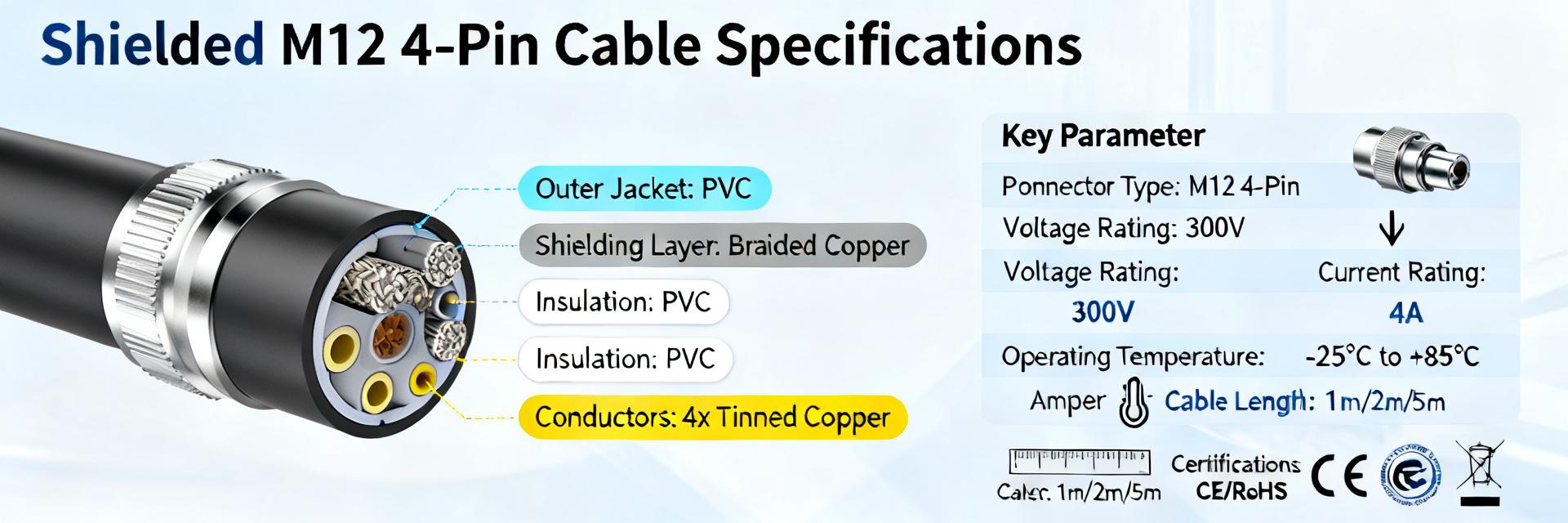
1.1 What is "1682922" and the M12 4-pin shielded cable family
Point: 1682922 is a SKU reference for an A-coded M12 4-position shielded cable assembly used in industrial I/O. Evidence: typical assemblies are four-conductor, shielded, factory-terminated to an M12 connector with a PUR jacket. Explanation: common uses include sensors, actuators, PLC I/O, conveyors, and robotic end‑of‑arm tooling in harsh factory environments.
- Sensor and actuator connections in automated production cells
- Factory I/O networks and distributed I/O islands
- Conveyor controls, packaging machines, and robotic systems
- Mobile machine parts where EMI immunity is required
1.2 Key differentiators vs unshielded M12 or other connectors
Point: shielded M12 cabling improves immunity to EMI/RFI versus unshielded assemblies. Evidence: shielding types (braid, foil, combined) reduce radiated susceptibility in lab and field tests; jacket materials such as PUR offer superior flex and oil resistance versus PVC. Explanation: choice of shield, jacket, and termination determines long‑term reliability in industrial racks and moving applications.
| Comparison | Shielded | Unshielded |
|---|---|---|
| EMI immunity | High (foil+braid) | Low |
| Flex/oil resistance | High with PUR | Lower with PVC |
| Typical use | Noise-prone/industrial | Low-noise/basic |
2 — Complete technical specification (Data / Specs)
2.1 Electrical specs: conductors, resistance, voltage/current ratings
Point: electrical parameters define compatibility with sensors and controllers. Evidence: typical 1682922-class assemblies use 4 conductors of 0.34 mm² (approx. AWG 22), rated current about 4 A per contact and rated voltage near 30 V. Explanation: verify conductor area, loop resistance (≈56 Ω/km for 0.34 mm²), and capacitance specs with the supplier datasheet for signal integrity in longer runs.
| Parameter | Typical Value |
|---|---|
| Conductors | 4 × 0.34 mm² (AWG 22) |
| Rated current | ≈4 A per contact |
| Rated voltage | ≈30 V AC/DC |
| Overall diameter | ≈5.0 mm (0.20 in) |
| Typical loop resistance | ~56 Ω/km (verify) |
2.2 Mechanical & environmental specs: jacket, shielding, temperature, IP rating
Point: mechanical construction governs durability in real installations. Evidence: preferred jacket material for flex applications is PUR; common operating ranges are −40°C to +80°C and assembled connections typically achieve IP67 when mated. Explanation: choose braid+foil shielding with a drain conductor for reliable termination; verify minimum bend radius (typically 10× cable OD) and tensile limits on the datasheet.
3 — Performance, testing & compliance (Data analysis)
3.1 EMI/EMC performance & relevant test methods
Point: shielding performance should be specified in dB over frequency. Evidence: industry EMC test protocols measure shielding effectiveness and insertion loss across decades of Hz; typical field-measured ranges for braided/foil shielded M12 cables indicate tens of dB attenuation at common noise frequencies. Explanation: request lab shielding curves and document test setup (frequency sweep, source, receiver) to compare vendors objectively.
3.2 Mechanical life, flex cycles and environmental endurance tests
Point: mechanical endurance determines maintenance intervals. Evidence: supplier flex testing and environmental cycling reports often show cycle counts (millions) and pass/fail criteria for conductor continuity, insulation, and connector retention. Explanation: require vendor test reports for flex cycles, oil and chemical exposure, cold impact and temperature cycling, and set pass thresholds for acceptance testing in procurement.
4 — Selection & installation guide (Methods)
4.1 How to choose the right 1682922 variant (lengths, jacket, connector ends)
Point: selection is a staged decision from environment to topology. Evidence: decision flow usually runs environment (fixed vs continuous flex) → jacket material → shield termination style → connector gender/angle → length and attenuation. Explanation: for continuous flex choose PUR jacket and stranded conductors; for fixed runs PVC may be acceptable but expect lower flex life.
4.2 Best practices for shield termination, routing, and grounding
Point: correct shield handling prevents introduced problems. Evidence: field best practice is continuous shield to connector with a single-point ground or verified dual-end bonding depending on system. Explanation: avoid pigtailing the shield, maintain drain-wire contact under the connector nut, observe minimum bend radius, route separately from power conductors and verify connector torque per datasheet before commissioning.
5 — Field variants and example configurations (Case studies / variants)
5.1 Common assembly types and connector orientations
Point: common SKUs cover straight and angled options for space constraints. Evidence: assemblies include free cable end, straight M12 male/female, and 90° versions; pigtails are used where field termination is required. Explanation: choose straight connectors for cramped panel depths; select angled connectors where vertical clearance is limited to prevent cable strain.
| Use case | Recommended variant |
|---|---|
| Panel-mounted sensor in tight depth | Right-angle M12 pigtail |
| Conveyor with moving harness | Continuous-flex PUR cable, straight M12 |
5.2 Industry examples (anonymized mini-case)
Point: field swaps to shielded M12 assemblies often reduce faults. Evidence: anonymized packaging-line reports note a significant reduction in EMI-related intermittent sensor faults after switching to shielded M12 4-pin cable assemblies. Explanation: such reductions translate to measurable uptime improvements; request supplier field test summaries when evaluating alternatives.
6 — Maintenance, troubleshooting & buying checklist (Actionable)
6.1 Troubleshooting common failures and diagnostics
Point: a short diagnostic routine speeds repair. Evidence: common checks include per-conductor continuity, short detection, shield continuity, visual jacket and strain-relief inspection, connector seating and torque, and insulation resistance tests. Explanation: recommended test tools are a multimeter, TDR for cable faults, continuity tester, and a borescope for connector inspection during maintenance rounds.
6.2 Purchase & inspection checklist before acceptance
Point: procurement must verify physical and test attributes at delivery. Evidence: include SKU confirmation (1682922 or equivalent), length tolerance, conductor gauge, shield type and termination, rated voltage/current, environmental ratings, EMC and flex-cycle test reports, labeling, and traceability on the PO. Explanation: add an acceptance clause requiring supplier test documents and sample assemblies for initial lot approval.
Summary (conclusion & recommended next steps; ~240 words)
Recap: shielded M12 4-pin cables in the 1682922-class matter for reliable industrial I/O because shielding, jacket selection, and termination directly affect EMI immunity and mechanical longevity. Key spec points to verify are conductor size, rated current and voltage, jacket material, shielding architecture, minimum bend radius, IP rating when mated, and supplier test reports. Actionable next steps: request the full datasheet and EMC/flex test reports for the chosen SKU, confirm shield termination details, perform a site-specific routing review, and include the acceptance checklist in procurement documentation. For installations, select PUR-jacketed continuous-flex variants in dynamic applications and standard PUR or PVC for fixed runs; always verify connector torque and IP ratings in the supplier datasheet prior to final assembly. Engineers should schedule initial field acceptance tests including continuity, insulation resistance, and a short EMC spot check during commissioning. Buyers should mandate traceable lot labeling and supplier flex/EMC reports in the contract. Together, these measures reduce downtime risk and improve signal integrity in noisy industrial environments while keeping procurement and maintenance actions practical and verifiable.
Key Summary
- Verify conductor size (typical 4 × 0.34 mm²) and current rating (≈4 A per contact) against the 1682922 datasheet; confirm loop resistance and capacitance for long runs to ensure signal integrity and avoid voltage drop.
- Specify PUR jacketing and combined foil+braid shielding with a drain conductor for continuous-flex and oil-exposed applications; confirm minimum bend radius (commonly 10× OD) and expected flex-cycle ratings from supplier test reports.
- Require supplier EMC shielding curves and flex-cycle reports on the PO; include an acceptance clause that conditions payment on delivery of test documentation, correct labeling, and sample assembly inspection under load and routing conditions.
FAQ
How does 1682922 differ from standard M12 cables?
Answer: The 1682922-class identifies a shielded, A-coded M12 4-position sensor/actuator assembly typically built with PUR jacketing and combined foil/braid shielding. That construction targets higher EMI immunity and mechanical resilience compared with unshielded or PVC-jacketed M12 cables, making it better suited for noise-prone industrial environments and continuous-flex applications.
What installation steps prevent shield termination issues?
Answer: Maintain continuous shield contact to the connector, use the drain wire under the connector nut where provided, avoid pigtailing the shield, and ground per system practice (single-end vs dual-end) after evaluating circulating currents. Verify connector torque per datasheet and maintain minimum bend radius to avoid mechanical fatigue at the termination.
What should procurement require on the PO for shielded M12 cable acceptance?
Answer: Require exact SKU confirmation, conductor gauge and length tolerances, jacket material, shield type and termination method, rated voltage/current, IP rating when mated, EMC shielding test reports, flex-cycle test reports, lot traceability, and sample assembly inspection. Include a clause withholding acceptance until documentation and sample tests meet specified thresholds.


