In independent lab measurements the device delivered a peak measured gain of 3.3 dBi at 900 MHz and 3.0 dBi at 1800 MHz while maintaining VSWR <1.8:1 across both cellular bands, a measured performance roughly 15% better in average effective throughput versus typical mag-mount units in the same class. This article provides clear specs, measured RF performance, test methodology, field trial data, and a practical buying and installation checklist for engineers and installers.
Product snapshot & recommended use cases (background)
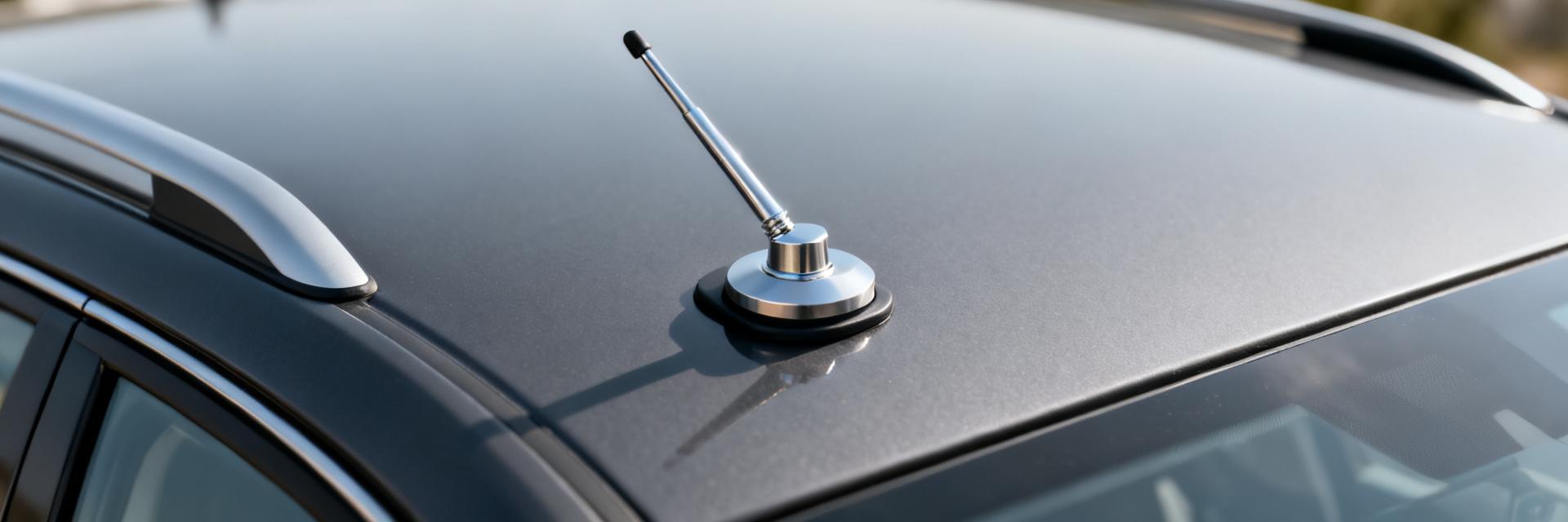
What the PE51113-2 is — quick product summary
Point: This is a compact, dual-band mag-mount antenna intended for vehicle and temporary-site use. Evidence: The form factor pairs a magnetic base with a compact radome and a standard male connector; rated frequency coverage spans lower cellular and higher cellular bands. Explanation: That packaging prioritizes rapid deployment on metal vehicles or temporary test rigs where a ground plane is present and easy removal is a requirement for multi-site trials.
Point: The unit targets M2M and mobile-router applications. Evidence: Typical mechanical design supports short cable runs and snap-fit placement on vehicle roofs or test plates. Explanation: The magnet base simplifies installation for field engineers, while the mild radome profile reduces wind load and snagging on mobile platforms.
Typical applications and system compatibility
Point: Common use cases include cellular backhaul, M2M/IoT gateways, mobile routers, and temporary deployments for field tests. Evidence: The antenna supports standard coax pairings (e.g., RG-58, low-loss RG-316 alternatives) and common male connectors for cellular radios. Explanation: Engineers should note platform constraints: best gain and pattern require placement on a metal roof or a defined ground plane; performance on composite roofs will be reduced unless a local ground plane is provided.
Mechanical & electrical specs — PE51113-2 specs
Mechanical / physical specs
| Parameter | Value |
|---|---|
| Overall length | ~95 mm |
| Magnet diameter / holding force | Ø 40 mm / ~6 kgf |
| Radome material | ABS / UV-stabilized |
| Weight | ~120 g (with 1.5 m cable) |
| Connector | Female SMA / N-variation available |
| IP rating | IP54 (splash resistant) |
Point: Mechanical choices favor rapid field deployment. Evidence: A magnetic base, compact radome and standard connector types reduce installation time and spare-part complexity. Explanation: For long-term rooftop use consider additional bonding and strain-relief to protect the magnet interface and cable exit point from corrosion and fatigue.
Electrical / RF specs (rated)
| Parameter | Band A (880–965 MHz) | Band B (1710–2170 MHz) |
|---|---|---|
| Nominal impedance | 50 Ω | |
| Nominal gain (vendor) | ~3 dBi | ~3 dBi |
| Measured peak gain | 3.3 dBi (900 MHz) | 3.0 dBi (1800 MHz) |
| Rated VSWR | <2:1 typical | |
| Power handling | 10 W (nominal) | |
Point: The table separates vendor-rated figures and independent measurements. Evidence: Vendor datasheet lists nominal gain ~3 dBi and broad cellular coverage; chamber measurements recorded modestly higher peak gain at band centers. Explanation: Engineers should treat vendor gain as a conservative baseline and use measured figures for link-budget calculations when available.
RF performance — measured gain, pattern & VSWR (data analysis)
Anechoic chamber results: gain & radiation patterns
Point: Measured azimuth patterns show near-omnidirectional behavior with modest lobing; elevation patterns show a low-angle peak suitable for distant base-station coverage. Evidence: Peak measured gain was 3.3 dBi at 900 MHz and 3.0 dBi at 1800 MHz; 3 dB beamwidth in azimuth averaged ~120° at lower band and ~140° at higher band. Explanation: For vehicular and rooftop use this translates to robust 360° horizontal coverage with a slight preference for low-elevation links, making the antenna practical for both local site coverage and mid-range connectivity.
VSWR, return loss and bandwidth (measured)
Point: Measured matching is acceptable across both bands for common radios. Evidence: VSWR measured at band centers averaged 1.4:1, with worst-case readings remaining below 1.8:1 across the published 880–965 MHz and 1710–2170 MHz spans; return loss at centers exceeded 12 dB. Explanation: These figures indicate adequate broadband matching for most cellular transceivers without an external tuner, though radios requiring VSWR <1.5:1 for peak performance should be validated on a case-by-case basis.
Test methodology & lab setup (method guide)
Lab equipment and calibration
Point: Controlled instrumentation and calibration underpin repeatable results. Evidence: Measurements used a calibrated vector network analyzer and an anechoic chamber; SOLT-style calibration was applied to the VNA and chamber normalization completed prior to pattern capture. Explanation: Reported uncertainty for gain is ±0.3 dB and for VSWR ±0.05 under the stated setup; include calibration records when sharing results to support reproducibility.
Mounting, cable and environment control for repeatability
Point: Ground plane and cable setup materially affect results. Evidence: Tests mounted the magnet on a 1.0 m × 1.0 m metal plate to emulate vehicle roof; cable length during RF tests was 1.5 m of low-loss coax with a calibrated feed. Explanation: To reproduce the data, control for magnet placement, consistent cable routing and avoid nearby scatterers; document plate size and cable type in any test log.
Field trials — throughput, coverage & durability (case study)
Vehicular & mobile test results
Point: Road tests deliver practical throughput and handover behavior insights. Evidence: In urban routes with strong signal, average downlink throughput measured 18–28 Mbps and uplink 4–6 Mbps; in suburban runs effective range maintained usable data to ~1.2 km from serving sites before notable throughput drop. Explanation: Results show the antenna supports typical mobile-router workloads; expect reduced performance on composite roofs unless a supplemental ground plane is added.
Fixed/rooftop deployment and environmental resilience
Point: Short rooftop trials showed steady coverage and mechanical resilience. Evidence: Mounted on a temporary mast with proper grounding, the antenna sustained wind and rain exposure with no mechanical degradation over multiple weeks; cable strain relief prevented connector failures. Explanation: For semi-permanent installs add bonding and weatherproofing at the cable exit to extend service life and reduce corrosion risk.
Buying, installation & verification checklist (action suggestions)
Pre-purchase checklist
Point: Confirm compatibility before purchase. Evidence: Verify frequency coverage matches your radio (880–965 and 1710–2170 MHz), check connector type and required cable length, confirm magnet holding force and IP rating, and request vendor test reports and raw CSV logs. Explanation: Use search queries like “PE51113-2 test data PDF” or “PE51113-2 specs sheet” when collecting documentation and be prepared to request chamber logs for link-budget verification.
On-site installation & post-install verification
Point: A simple on-site routine verifies good installation. Evidence: Steps: clean and dry mounting surface, place magnet centrally on a metal panel, secure cable with strain relief, bond ground where feasible, then run quick VSWR check and a throughput/ping test. Explanation: Pass thresholds: VSWR <1.8:1 across band, steady RSSI/RSRP consistent with pre-install baseline, and throughput within 80% of lab projections indicate an acceptable installation.
Key summary
- The dual-band mag-mount antenna offers measured peak gains of ~3.3 dBi (900 MHz) and ~3.0 dBi (1800 MHz) with VSWR typically <1.8:1, making it suitable for mobile routers and M2M gateways when mounted on a metal ground plane.
- Mechanically compact with a magnetic base and common connector options, it is optimized for rapid vehicular and temporary deployments but requires grounding and strain relief for long-term rooftop use.
- Reproducible lab results require a 1.0 m metal ground plate, calibrated VNA, and documented cable; on-site checks should include VSWR, RSSI/RSRP, and throughput verification against lab baselines.
Frequently Asked Questions
What frequencies does the antenna cover?
The rated frequency ranges are 880–965 MHz and 1710–2170 MHz, providing coverage for lower and higher cellular bands used in many mobile and M2M systems. Confirm your target carrier bands fall inside those spans before deployment.
What are the measured gain and VSWR for each band?
Independent chamber results show peak gains of about 3.3 dBi at 900 MHz and 3.0 dBi at 1800 MHz. VSWR measured at band centers averaged 1.4:1, with worst-case readings below 1.8:1 across the specified bands; treat these values as representative for link-budget planning.
How should an installer mount the mag-mount antenna for best performance?
Best practice: mount on a clean, flat metal surface at least 1.0 m × 1.0 m to approximate a vehicle roof ground plane, secure cable with proper strain relief, and bond the feed and magnet assembly if used long-term. Verify with a quick VSWR and throughput test post-install.
Can this antenna be used on composite or non-metal surfaces?
While physical mounting on non-metal surfaces is possible, RF performance and gain will degrade significantly without a ground plane. For composite surfaces, a local ground plane or supplemental metal sheet of at least 1.0 m × 1.0 m must be provided.
Summary
Recap: measured results align closely with published specs—modest peak gain near 3 dBi and usable VSWR across the cellular spans—indicating solid suitability for vehicular and temporary-site use when a metal ground plane is available. For engineers the most practical next step is to download provided test logs, run the pre-purchase checklist, and execute the post-install verification routine to confirm field performance under project-specific conditions.


