Datasheet figures show this 5‑position, shielded PUR cable is a common choice where reliable M12 connections and robust environmental resistance are required. This article gives a concise, actionable reference for the 1682964 sensor/actuator cable: full technical context, explicit pinout, wiring examples, installation best practices, and stepwise troubleshooting guidance to support correct selection and field use.
The goal is practical clarity: present typical cable specs and mechanical limits, a clear pin mapping table and wiring examples, and a short selection/ordering checklist installers can use immediately. Where exact numeric tolerances matter, verify values against the manufacturer's datasheet for the specific part number and length variant.
Product overview & intended uses (background introduction)
Key features at a glance
- 5 cores, A‑coded M12 female connector, pre-assembled cable assembly (standard length variants such as 1.5 m common).
- Shielded construction: tinned copper braid with drain conductor for effective EMI protection.
- Jacket material: PUR (polyurethane) for abrasion, oil and chemical resistance; typically halogen‑reduced or halogen‑free variants noted on datasheet.
- Typical conductor cross‑section used for sensor/actuator cables (verify exact value on datasheet).
- Use critical selection note: choose braid vs. foil shielding level based on EMI environment and flex life needed.
Typical applications & system roles
These cables are used for sensors, actuators, short fieldbus segments, and I/O cabling on conveyors, robotic end‑of‑arm tooling, and distributed I/O racks. Shielding reduces radiated and conducted EMI in noisy motor/drive areas; PUR jackets endure repeated flex cycles and resist oils/chemicals in industrial cells. A typical scenario: a 1.5 m pre‑wired M12 run from sensor cluster to IO module delivers reliable 24 VDC I/O with low maintenance demands.
Technical specifications breakdown (data analysis)
Electrical specifications (cable specs)
Typical electrical data to confirm on the datasheet: conductor cross‑section (mm²), nominal voltage rating (V), maximum DC resistance (Ω/km), insulation resistance (MΩ·km), and rated current per conductor (A). Present these as a concise spec table so installers can quickly match current and voltage needs to conductor size and length.
| Parameter | Typical / Example value | Notes |
|---|---|---|
| Core count | 5 | M12 A‑coded |
| Conductor | ~0.34 mm² (verify) | Check datasheet for exact mm² per variant |
| Rated voltage | typically industrial low‑voltage (confirm) | Used in 24 VDC systems; confirm insulation rating |
| DC resistance | ~50–60 Ω/km (typical for 0.34 mm²) | Exact Ω/km in datasheet |
| Shield | Tinned copper braid + drain | Preferred for repeated flex & EMI |
Mechanical & environmental specs
Key mechanical specs to check: PUR jacket temperature range (flex vs. fixed), minimum bending radius, flex cycle rating, abrasion and oil resistance class, jacket color / RAL code, and IP rating for assembled connectors. Always verify whether the part is specified for continuous flex or fixed routing and confirm environmental certifications for your site (oil, UV, halogen content).
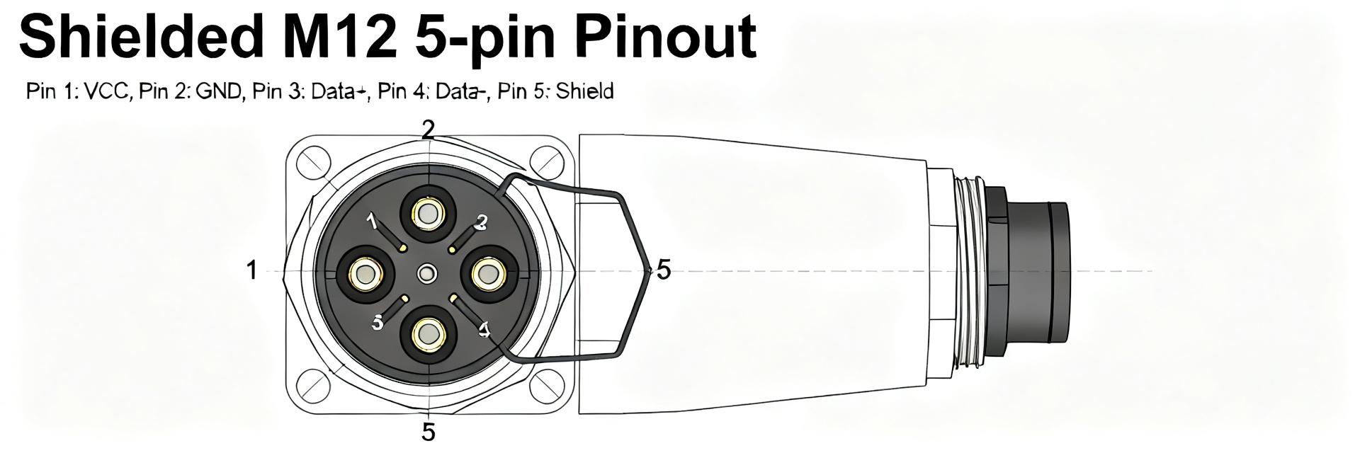
Pinout & wiring guide for 1682964 sensor/actuator cable (data + practical)
Pin mapping (pin number, wire color, function)
Below is a standard 5‑pin A‑coded M12 mapping used in many sensor/actuator cables. Colors and functions can vary by batch—always confirm against the specific datasheet and continuity test the assembly before installation.
| Pin | Nominal color | Standard function | Notes |
|---|---|---|---|
| 1 | brown | +V (supply) | Main positive supply to sensor/actuator |
| 2 | white | Signal / IO1 | Digital input/output or signal line |
| 3 | blue | 0 V (ground) | Return/negative supply |
| 4 | black | Signal / IO2 | Optional second IO or control |
| 5 | gray | Signal / IO3 | Auxiliary function |
Wiring examples & shield termination
Example A — sensor with single‑ended 24 V supply: connect pin 1 to +24 V, pin 3 to 0 V, pin 2 to the sensor signal input. Example B — actuator with separate power and signal: run power on pin 1/3 and route control on pins 2/4 as discrete outputs; ensure current capacity is adequate for actuator load. For shield termination, connect the drain to chassis or controller ground at one end only to avoid ground loops; tie shield to local chassis at the machine frame for best EMI control.
ASCII M12 (front) layout, pins seen on connector face:
  _____
 / 5 4 \
| 1 2 3 |
 \_____/
Pin order: 1 (brown) top-left, 2 (white) top-right, 3 (blue) bottom-right, 4 (black) top-center, 5 (gray) bottom-left
Installation, testing & troubleshooting (method/action)
Installation best practices
Route sensor/actuator cables separately from large power conductors and motor feeds; maintain recommended separation distance and use cable trays or conduits. Respect minimum bend radius and use strain relief at M12 connectors. Torque connector nuts per datasheet, use appropriate cable glands, and secure cables at regular intervals to avoid repeated sharp bends. Before energizing, verify pin mapping and shield termination.
Common faults & diagnostic tests
Troubleshooting flow: visual inspection → continuity checks → insulation test → functional signal test. Use a multimeter to check continuity and shorts, a megger for insulation resistance, and an oscilloscope or fieldbus tester for signal integrity problems. Typical symptoms: intermittent signals often indicate broken conductor or connector contact; high noise suggests missing or improper shield termination.
Selection & procurement checklist (actionable buying guide)
How to choose the right variant
Decide flex vs. fixed routing first, then match conductor size to required load and length, add margin to current/temperature ratings, and select shielding level for EMI environment. Choose PUR jacket for oil and abrasion resistance and order pre‑terminated M12 assemblies for faster installation. Account for spare length and consider pre‑wired assemblies if connector orientation (right/straight) matters.
Datasheet & ordering checks
Before ordering confirm: exact part number and length, conductor AWG/mm², shield type and drain availability, jacket material and color, bending radius, flex life rating, IP rating with mating connector, and termination orientation. Verify connector coding and pinout consistency with the system controller to avoid field swaps.
→ Summary
- Confirm the exact 1682964 sensor/actuator cable variant on the manufacturer datasheet before purchase—verify conductor size, shielding, and flex rating to match application needs and avoid surprises in current capability and bend radius.
- Use the provided pin mapping and wiring examples to standardize connections: pin 1 = +V, pin 3 = 0 V, pins 2/4/5 for signals; terminate shield to chassis at a single point to control EMI without creating ground loops.
- Follow installation best practices—separate routing from power, respect bend radius and torque values, and perform continuity and insulation testing after installation to ensure long‑term reliability.
Common questions
What is the standard pinout for the 1682964 sensor/actuator cable?
The common mapping for this 5‑pin A‑coded M12 assembly is: pin 1 brown = +V, pin 3 blue = 0 V, pins 2/4/5 = signal or IO lines (white, black, gray). Always confirm against the specific part datasheet and verify continuity on arrival, as color coding can vary by batch.
How should the shield of the 1682964 sensor/actuator cable be terminated?
Terminate the shield to chassis or controller ground at one end only (typically the controller end) to avoid ground loops. Use the cable’s drain conductor for a secure connection and bond the shield to the machine frame for best EMI suppression; avoid tying shields to multiple isolated grounds.
Can this cable be used for continuous flex applications?
Some PUR‑jacketed assemblies are specified for continuous flex, others for fixed installation. Check the datasheet flex‑life rating and minimum bending radius. If continuous motion is required, select the variant explicitly rated for moving applications and plan routing with adequate bend radius and strain relief.
What are the primary advantages of the PUR jacket in industrial environments?
The Polyurethane (PUR) jacket provides superior mechanical protection, characterized by extreme abrasion resistance, high tear propagation resistance, and excellent chemical compatibility with mineral oils, synthetic lubricants, and industrial coolants. It is typically halogen-free and handles dynamic flex cycles much better than PVC.


