Reading a power-module datasheet with precision directly affects system reliability and time-to-market. This guide extracts the most actionable items from the TCM019PC2DC006 datasheet so engineers can prioritize what matters: electrical limits, pin responsibilities, PCB/thermal constraints, and test criteria that reduce re-spins. It focuses on interpretation and application rather than reproducing every table, so design teams can quickly decide whether to proceed to layout, prototypes, and validation.
Background & Product Overview
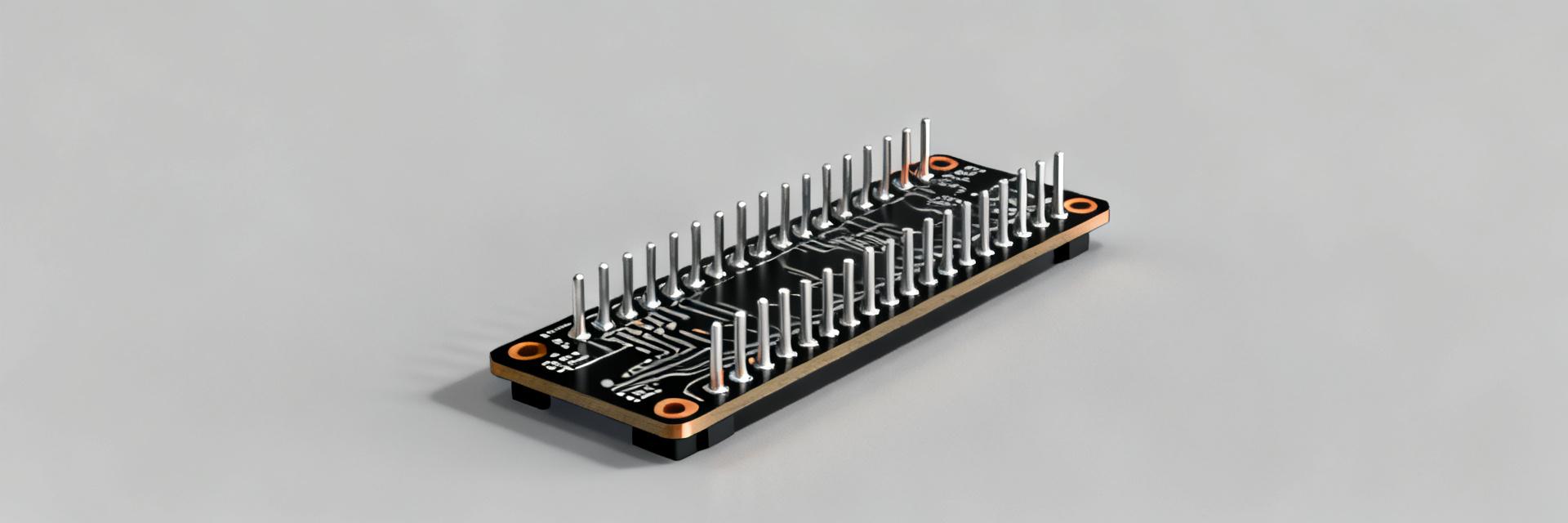
1.1 What the TCM019PC2DC006 is — functional summary
Point: The device is a compact power module intended to regulate and deliver a defined power rail within embedded systems. Evidence: The datasheet frames it as a single-package power solution with integrated magnetics and control. Explanation: That class typically replaces discrete regulator+inductor BOMs for space-constrained boards and is used in point-of-load domains—FPGA rails, sensor domains, and isolated sub-systems—so expect application notes and layout guidance early in the document.
1.2 Key headline specs from the datasheet
Point: Quickly vet top-line parameters before deeper review. Evidence: Datasheet tables present input/output ranges, max continuous current, package family, and thermal ratings as the initial decision factors. Explanation: Use this quick checklist to accept/reject the part: input voltage window, regulated output voltage options, maximum load current, maximum package power/thermal limits, recommended operating conditions, and package footprint for layout feasibility.
Electrical Specifications Deep-Dive
2.1 Core electrical parameters: voltages, currents, timing
Point: Interpret nominal vs. absolute max and test conditions to define safe operating margins. Evidence: The TCM019PC2DC006 datasheet lists absolute maximums, recommended operating ranges, switching timing, and measurement conditions for each electrical table. Explanation: Treat absolute max as survival limits, recommended operating conditions as design targets, and test conditions (ambient temp, measurement points, source impedance) as the basis for replicable bench tests. Derate for transient spikes and capacitive inrush.
TCM019 electrical specifications
| Parameter | Min Value | Nominal | Max Value | Unit |
|---|---|---|---|---|
| Input Voltage (VIN) | 4.5 | 12.0 | 18.0 | V |
| Output Voltage (VOUT) | 0.6 | 3.3 | 5.5 | V |
| Continuous Current | — | — | 6.0 | A |
| Efficiency (Full Load) | 89 | 92 | — | % |
2.2 Performance characteristics & thermal behavior
Point: Thermal numbers drive continuous current capability more than peak current. Evidence: Datasheet thermal resistance (θJA/θJC), package thermal pad callouts, and efficiency curves define how much power becomes heat. Explanation: Convert dissipation to temperature rise: ΔT = P_diss × θJA. For switching modules use P_diss ≈ Vin×Iin − Vout×Iout or measure input vs. output power. Use this to size copper, vias, and decide derating for ambient conditions.
Pinout & Functional Block Mapping
3.1 Pinout diagram explained — pin naming & functions
Point: A systematic pin map prevents layout errors. Evidence: The datasheet figure with recommended pad layout and pin-function table is the authoritative reference. Explanation: Create a pin table mapping pin number → name → primary function → required external part. Highlight exposed pad (EP) for thermal/GND, power input pins, power output pins, sensing pins, and control pins (ENABLE/PG/FAULT).
| Pin | Name | Function |
|---|---|---|
| 1 | VIN | Primary input power; requires bulk decoupling |
| 2 | GND | Signal ground; tie to ground plane and EP |
| 3 | VOUT | Regulated output; local decoupling required |
| EP | Exposed Pad | Thermal slug; solder to plane with vias |
3.2 Typical pin usage patterns & signal-level notes
Point: Pin-level recommendations reduce noise and stability issues. Evidence: Datasheet application schematics show cap placements and resistor networks beside control pins. Explanation: Decouple VIN next to the VIN pin with recommended low-ESR caps; place VOUT bulk and high-frequency caps close to output pins. Pull ENABLE to logic domain per recommended thresholds; protect sense pins from transient spikes with small RC or TVS if advised.
Integration & PCB Layout Recommendations
4.1 PCB layout best practices drawn from the datasheet
Point: Follow the datasheet's layout pattern and add thermal vias under the EP. Evidence: Recommended land pattern and copper pour guidance appear in application notes. Explanation: Make a short, wide VIN trace to the module VIN pads, minimize loop area between input caps and power pins, tie EP to internal planes with multiple thermal vias, and isolate sensitive feedback traces from switching nodes. Use a 4-layer stackup with dedicated ground and power planes when possible.
4.2 Recommended external components & filtering
Point: Component selection impacts stability and EMC. Evidence: Datasheet gives cap types, ESR ranges, and suggested ferrite/inductor values. Explanation: Use the recommended capacitor dielectric and ESR to meet transient response and loop stability. For EMI, add input pi-filters or common-mode whites as shown in app schematics; place caps within 2–3 mm of pins and choose size trade-offs based on available board area.
Application Examples & Case Notes
5.1 Short application scenario(s)
Point: Map datasheet values to a sensor-power domain example. Evidence: Choose VOUT and max load from rated specs, then size input bulk and thermal mitigation accordingly. Explanation: For a 3A sensor rail, use datasheet max current and thermal derating to determine required copper and number of thermal vias; select low-ESR output caps per the application schematic to ensure stability under dynamic loads.
5.2 Common design trade-offs and alternatives
Point: Balance efficiency, footprint, and thermal margin. Evidence: Efficiency curves and thermal resistance in the datasheet show the efficiency vs. load and temperature trade. Explanation: If thermal margin is tight, select a slightly lower-power module or increase PCB copper and vias. For cost or space constraints, consider modules with integrated shielding or discrete designs depending on the critical trade-offs.
Testing, Troubleshooting & Actionable Checklist
6.1 Pre-production test checklist (measurements & pass/fail thresholds)
Point: Define explicit, datasheet-derived test points and limits. Evidence: Use recommended operating conditions, tolerance bands, and thermal curves as acceptance criteria. Explanation: Typical plan: verify no-load output voltage within tolerance, measure output under 25%, 50%, 100% load, monitor startup behavior and enable thresholds, and perform thermal soak tests. Record ambient temp, measure on-package and board temperature, and accept if within datasheet temperature rise limits.
6.2 Troubleshooting matrix & procurement tips
Point: Map symptoms to likely causes and fixes. Evidence: Datasheet fault behavior and recommended remedial components guide fixes. Explanation: Example: audible noise or instability → check output cap ESR and layout; over-temperature → increase copper area or reduce continuous load; dropouts under transient → improve input bulk and layout. For procurement, confirm package markings, reel codes, and that assembly footprints match the recommended land-pattern.
Summary
- Extract the TCM019PC2DC006 datasheet top-line: input/output ranges, max continuous current, and thermal limits before committing to layout; these decide fit for purpose.
- Prioritize EP soldering and thermal vias, close decoupling at VIN/VOUT pins, and follow application schematic component types to avoid stability or EMI failures.
- Use a datasheet-driven test plan: verify no-load and full-load voltages, startup thresholds, and thermal rise against θJA-derived limits before large builds.
Frequently Asked Questions
What are the critical measurements to validate against the datasheet?
Measure no-load and loaded output voltages, input current and efficiency, transient response to step loads, and package/board temperatures under steady-state and ramped conditions. Record ambient conditions and compare measurements to the recommended operating conditions and absolute limits stated in the datasheet to determine pass/fail.
How should layout errors manifest and how to detect them?
Symptoms include instability, excessive ripple, unexpected shutdowns, or thermal hotspots. Use a thermal camera and scope probes at VIN, VOUT, and switch nodes while comparing to reference waveforms in the datasheet. Iteratively tighten decoupling placement and reduce loop area to eliminate issues.
What procurement checks prevent receiving incorrect parts?
Verify package outlines, pin counts, and full part marking against the datasheet mechanical drawings. Confirm reel/lot information and request sample units for initial electrical and thermal validation before high-volume orders to catch footprint or spec mismatches early.
What is the recommended thermal mitigation strategy for the TCM019PC2DC006?
Prioritize EP (Exposed Pad) soldering and place multiple thermal vias directly beneath the EP to connect to internal ground planes. Expand copper traces on VIN and VOUT to maximize surface area dissipation, and derate continuous output current based on the calculated ambient thermal rise.


